配件详情
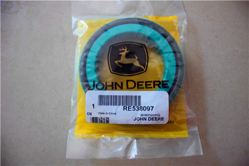
麦克福斯约翰迪尔发动机零配件
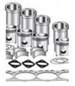
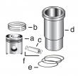
约翰迪尔 6081 高压缩活塞
|
|
|
发动机和设备型号
|
高压缩活塞
4801 4803
孔径:
4.56 in 116 mm
销径 Ø:
1.8742 in (+/- .0002) = 47 mm
发动机型号:
6081HDW08
6081HDW09
6081HDW13
6081HRW25
6081HRW31
6081HRW32
6081HRW33
6081HRW34
6081HRW41
6081HRW42
6081HRW43
6081HT002
6081HT008
6081HTJ05
6081HTJ06
6081HTJ07
6081HTJ08
6081HZ009
|
|
|
强鹿JOHN DEERE柴油机配件、发动机配件、发电机组:
H0000351、ECC105017、C105003、ECC105028、ECC065003、B125003、ECB125011,RE522528、RE519774、RE532628、RE518176、RE507980、RE518503、RE522515、RE504836、RE509031、RE509032、RE59754、RE507284、RE59754、RE519626、RE518977、RE508202、RE58935mounting torque 130 n?m (95 lb-ft) bracket-to-cylinder head cap screws surge tank-to-mounting bracket cap torque 50 n?m (37 lb-ft) screws surge tank fuel lines torque 24 n?m (18 lb-ft) fuel supply pump&camshaft torque 4 n?m (3 lb-ft) drive coupler set screws fuel supply pump mounting bracket torque 50 n?m (37 lb-ft) cap screws fuel supply pump-to-bracket torque 25 n?m (18 lb-ft) ctm188 (20mar01) 06-200-4 powertech 10.5 l & 12.5 l level 6 fuel system 032001 pn=470 continued on next page repair specifications 06 200 5 ouo1004,0000be2 –19–03nov00–2/2 item measurement specification fuel line orfs fittings torque 24 n?m (18 lb-ft) dual rail fuel manifold-to-head torque 35 n?m (26 lb-ft) fuel lines-to-fuel manifold torque 24 n?m (18 lb-ft) fuel return check valve (on torque 33 n?m (24 lb-ft) manifold) electronic unit injector hold-down initial torque 20 n?m (15 lb-ft) clamp cap screws electronic unit injector hold-down final torque-turn 90—100° clamp cap screws electronic unit injector wiring torque 2 n?m (1.75 lb-ft) (18 lb-in.) harness connector nuts fuel line clamps torque 5 n?m (4 lb-ft) electronic unit injector torque 35 n?m (26 lb-ft) harness-to-shaft clamps electronic unit injector wiring torque 25 n?m (18 lb-ft) connector bracket-to-head electronic unit injector adjusting torque 65 n?m (48 lb-ft) screw lock nut timing pin plug in cylinder block torque 33 n?m (24 lb-ft) fuel filter outlet line torque 24 n?m (18 lb-ft) ctm188 (20mar01) 06-200-5 powertech 10.5 l & 12.5 l level 6 fuel system 032001 pn=471 repair specifications 06 200 6 ouo1004,0000c3b –19–18dec00–1/2 single rail fuel system specifications item measurement specification fuel filter assembly fuel line orfs fittings torque 24 n?m (18 lb-ft) fitting (fuel return from rail) torque 33 n?m (24 lb-ft) fuel pressure sen*** torque 14 n?m (124 lb-in.) fitting (fuel pressure sen***) torque 14 n?m (124 lb-in.) fitting (fuel return to tank) torque 33 n?m (24 lb-ft) fitting (fuel outlet to supply torque 33 n?m (24 lb-ft) pump) fitting (fuel inlet from tank) torque 33 n?m (24 lb-ft) fuel primer torque 14 n?m (124 lb-in.) fuel primer-to-fuel filter housing torque 11 n?m (97 lb-in.) adapter (single rail fuel system) fuel temperature sen*** torque 14 n?m (124 lb-in.) check valve&fitting torque 33 n?m (24 lb-ft) diagnostic test port&fitting torque 14 n?m (124 lb-in.) filter housing plugs torque 7 n?m (62 lb-in.) filter cap torque 11 n?m (100 lb-in.) water separator bowl torque 6 n?m (55 lb-in.) fuel filter return tube (inside torque 20 n?m (15 lb-ft) filter housing) fuel filter assembly-to-bracket torque 50 n?m (37 lb-ft) cap screws fuel filter bracket-to-cylinder torque 65 n?m (48 lb-ft) block cap screws ctm188 (20mar01) 06-200-6 powertech 10.5 l & 12.5 l level 6 fuel system 032001 pn=472 continued on next page repair specifications 06 200 7 ouo1004,0000c3b –19–18dec00–2/2 item measurement specification low pressure regulating torque 18 n?m (13 lb-ft) valve-to-filter housing high pressure regulating torque 14 n?m (124 lb-in.) valve-to-filter housing 100 micron internal filter housing torque 5 n?m (44 lb-in.) screen fuel filter check valve to fuel filter torque 33 n?m (24 lb-ft) housing fuel supply pump&camshaft torque 4 n?m (3 lb-ft) drive coupler set screws fuel supply pump mounting bracket torque 50 n?m (37 lb-ft) cap screws fuel supply pump-to-bracket torque 25 n?m (18 lb-ft) fuel line orfs fittings torque 24 n?m (18 lb-ft) electronic unit injector hold-down initial torque 20 n?m (15 lb-ft) clamp cap screws electronic unit injector hold-down final torque-turn 90—100° clamp cap screws electronic unit injector wiring torque 2 n?m (18 lb-in.) harness connector nuts fuel line clamps torque 5 n?m (44 lb-in.) electronic unit injector torque 35 n?m (26 lb-ft) harness-to-shaft clamps electronic unit injector wiring torque 25 n?m (18 lb-ft) connector bracket-to-rear of head electronic unit injector adjusting torque 65 n?m (48 lb-ft) screw lock nut timing pin plug in cylinder block torque 33 n?m (24 lb-ft) ctm188 (20mar01) 06-200-7 powertech 10.5 l & 12.5 l level 6 fuel system 032001 pn=473 repair specifications 06 200 8 ouo1004,0000bde –19–03nov00–1/1 electronic engine control system specifications item measurement specification ecu mounting bracket-to-cylinder torque 68 n?m (55 lb-ft) block lower cap screws ecu mounting bracket-to-cylinder torque 110 n?m (81 lb-ft) block upper front cap screw coolant temperature sen*** torque 10 n?m (7.5 lb-ft) fuel temperature sen***-to-fuel torque 10 n?m (7.5 lb-ft) manifold (dual rail fuel system) fuel temperature sen***-to-fuel torque 14 n?m (10 lb-ft) filter housing (single rail fuel system) fuel pressure sen***-to-fuel filter torque 14 n?m (10 lb-ft) housing (single rail fuel system) water-in-fuel sen***-to-water torque 14 n?m (10 lb-ft) separator bowl (single rail fuel system) engine oil pressure sen*** torque 9 n?m (80 lb-in.) engine oil pressure sen*** torque 11 n?m (97 lb-in.) adapter-to-filter housing manifold air temperature (mat) torque 10 n?m (7.5 lb-ft) sen*** manifold absolute pressure (map) torque 7 n?m (5 lb-ft) sen*** camshaft position sen*** torque 14 n?m (10 lb-ft) crankshaft position sen*** spotface distance 36.7—38.2 mm (1.44—1.50 in.) (mounting surface)-to-crankshaft timing wheel tooth crankshaft position sen*** torque 14 n?m (10 lb-ft) ctm188 (20mar01) 06-200-8 powertech 10.5 l & 12.5 l level 6 fuel system 032001 pn=474 group 210 diagnostic specifications rg,rg34710,1609 –19–30sep97–1/1 fuel system diagnostic specifications item specification fuel supply pressure on a dual rail fuel system normal (idle) 410–480 kpa (4.1–4.8 bar) (60–70 psi) cranking (minimum 200 rpm) .. 70–170 kpa (0.7–1.7 bar) (10–25 psi) fuel supply pressure on a single rail fuel system normal (idle) 410-555 kpa (4.1—5.5 bar) (60—80 psi) cranking (minimum 200 rpm) .. 135—175 kpa (1.35—1.75 bar) (20—25 psi) rated speed 480—620 kpa (4.8—6.2 bar) (70—90 psi) fuel system o-ring-face-seal fittings on dual rail fuel system: final filter-to-fuel manifold ..... 24 n?m (18 lb-ft) transfer pump-to-final filter ... 24 n?m (18 lb-ft) 06 210 1 ctm188 (20mar01) 06-210-1 powertech 10.5 l & 12.5 l level 6 fuel system 032001 pn=475 diagnostic specifications 06 210 2 rg,rg34710,1611 –19–30sep97–1/4 torque curve selection john deere applications note: 6750/6850 self-propelled forage harvester applications only use torque curve #0. note: 450c lc excavator only uses torque curve #1. torque curve selection for 9200, 9300, 9400 wheel tractors torque pst 12 speed 24 speed mst curve mst on dst 0 when none of when none when none of the the below of the below below conditions are conditions are conditions met met are met 1 when in gear when in gear when in gears a3h 3f 3f/b1l 2 3-pt. hitch 3-pt. hitch 3-pt. hitch lowered lowered lowered or or/vehicle speed less vehicle speed vehicle than 0.5 mph and less than 0.5 speed less pto engaged mph&pto than 0.5 mph or engaged&pto when in gears a1l, engaged a1h, a2l, a2h, a3l, arl,/arh 3 when in gears not used not used 1f, 2f, 1r torque curve selection for 9300/9400 track tractors (ltvs) torque curve conditions for torque curve on dst 0 when torque curve 1&2 conditions are not met 1 when in gears a3h/b1l 2 when 3-pt. hitch lowered&pto engaged or when in gears a1h, a2l, a2h, a3l, arl, or arh 3 not used 4 when torque curve 1&2 conditions not met and steering boost is activated 5 when in gears a3h/b1l&steering boost activated. 6 when in gears a1l, a1h, a2l, a2h, a3l, arl,/arh&steering boost activated 7 not used torque curve selection for 744h/mh loaders torque curve on conditions for torque curve dst not a proper torque curve. used when can 0 is used. 1 744h when in gears 2-4 2 744h/mh when in gear 1 3 744mh when in gears 2-4 torque curve selection for combines torque curve on conditions for torque curve dst 0 default - error in can communication 1 normal operating conditions auger on (times out after three minutes of 2 continuous auger operation) 3 separator engagement only oem&marine applications torque curve selection for marine applications torque curve rated speed jumper wire on program on dst performance connector: 0 2100 rpm no jumper wires installed 1 2000 rpm jumper wire installed between terminals c and h only 2 1900 rpm jumper wire installed between terminals b and j only 3 1800 rpm jumper wire installed between terminals a and k. ctm188 (20mar01) 06-210-2 powertech 10.5 l & 12.5 l level 6 fuel system 032001 pn=476 continued on next page diagnostic specifications 06 210 3 rg,rg34710,1611 –19–30sep97–2/4 rg10694 –un–06jan00 performance program connector torque curve selection for oem applications (6105af001, 6105hf001, 6125af001,&6125hf001) torque curve engine speed jumper wire on on dst program performance connector: 1 intermittent power curve no jumper wires #1 installed 2 intermittent power curve no jumper wires # 1 with “minimum” installed power bulge (torque curve 1 times out and torque curve 2 is selected) 3 derated intermittent jumper wire installed power curve #3 between terminals b and j only 4 continuous power curve jumper wire installed #2 between terminals a and k only 5 continuous power curve jumper wire installed #2 with “minimum” power between terminals a bulge (torque curve 4&k only times out&torque curve 5 is selected) 6 derated continuous jumper wire installed power curve #4 between terminals b and j&terminals a and k continued on next page ctm188 (20mar01) 06-210-3 powertech 10.5 l & 12.5 l level 6 fuel system 032001 pn=477 diagnostic specifications 06 210 4 rg,rg34710,1611 –19–30sep97–3/4 torque curve selection for oem engine applications (6125hf070) torque curve engine speed jumper wire on on dst program performance connector: 1 intermittent power curve no jumper wires #1 installed 2 intermittent power curve no jumper wires # 1 with “minimum” installed power bulge (torque curve 1 times out and torque curve 2 is selected) 3 continuous power curve jumper wire installed #1 between terminals a and k only 4 intermittent power curve jumper wire installed #2 between terminals b and j only 5 intermittent power curve jumper wire installed #2 with “minimum” power between terminals b bulge (torque curve 4&j only times out&torque curve 5 is selected) 6 continuous power curve jumper wire installed #2 between terminals b and j&terminals a and k rg,rg34710,1611 –19–30sep97–4/4 rg10694 –un–06jan00 performance program connector ctm188 (20mar01) 06-210-4 powertech 10.5 l & 12.5 l level 6 fuel system 032001 pn=478 diagnostic specifications 06 210 5 dpsg,rg40854,481 –19–10dec99–1/2 governor droop mode selection note: desired speed governor&max. speed governor are parameters that are listed in the dst. a number is located next to each of these parameters. use the following tables to determine if the correct governor has been selected with respect to the conditions of the application. note: on 450c lc excavator applications, desired governor curve #0 is the only governor used. john deere applications desired speed governor selection for 9200, 9300, 9400 wheel tractors&9300&9400 ltvs mode selected conditions: 0 normal droop 1 field cruise with isochronous governor 4 field cruise with crank error max. speed governor selection 9200, 9300, 9400 wheel tractors&9300&9400 ltvs mode selected conditions: 9 normal droop (at 2240 rpm, becomes isochronous) 10 pto/hitch down operation. desired speed governor selection for 744h/mh&lx 230 loaders mode selected conditions: 0 normal droop max. speed governor selection for 744h/mh&lx 230 loaders mode selected conditions: 9 normal droop desired speed governor selection for 6750&6850 self-propelled forage harvesters mode selected conditions: 0 droop for low speeds (mode 0 is selected until 1650 rpm when speed increases&below 1450 rpm when speed is decreases) 1 droop for high speeds (mode 1 selected at 1650 rpm when speed increases&1450 rpm when speed decreases) max. speed governor selection for 6750&6850 self-propelled forage harvesters mode selected conditions: 9 normal droop desired speed governor selection for combines mode selected conditions: 0 normal conditions with isochronous governor max. speed governor selection for combines mode selected conditions: 9 normal when not in 3rd gear drooped governor 10 3rd gear at 1870 rpm with isochronous governor continued on next page ctm188 (20mar01) 06-210-5 powertech 10.5 l & 12.5 l level 6 fuel system 032001 pn=479 diagnostic specifications 06 210 6 dpsg,rg40854,481 –19–10dec99–2/2 rg10694 –un–06jan00 performance program connector oem&marine applications note: in order for the isochronous governor to be selected, terminals e&f on the performance program connector must be connected by a jumper wire. desired speed governor selection for oem applications mode selected conditions: 0 normal droop 2 isochronous all speed 5 cruise control max. speed governor selection for oem applications mode selected conditions: 9 drooped high speed governor 10 isochronous governor at high idle desired speed governor selection for marine applications mode selected conditions: 0 torque curve 0 droop 1 torque curve 1 droop 2 torque curve 2 droop 3 torque curve 3 droop 4 torque curve 0 with isochronous governor 5 torque curve 1 with isochronous governor 6 torque curve 2 with isochronous governor 7 torque curve 3 with isochronous governor 10 torque curve 0 with isochronous governor with crank error 11 torque curve 1 with isochronous governor with crank error 12 torque curve 2 with isochronous governor with crank error 13 torque curve 3 with isochronous governor with crank error max. speed governor selection for marine applications mode selected conditions: 9 normal droop ctm188 (20mar01) 06-210-6 powertech 10.5 l & 12.5 l level 6 fuel system 032001 pn=480 diagnostic specifications 06 210 7 ctm188 (20mar01) 06-210-7 powertech 10.5 l & 12.5 l level 6 fuel system 032001 pn=481 diagnostic specifications dpsg,rg40854,478 –19–10dec99–1/2 10.5 l & 12.5 l oem application electronic control system wiring diagram se3-electronic engine control unit (ecu) john deere level vi engine control unit (ecu) 050 performance program connector (ppc) +5v excitation torque curve select 1 torque curve select 2 isoc gov 933 934 max speed select 002 bat 422 starter relay solenoid 412 acc 012 ign +12v/+24v 938 937 416 414 414 012 012 se2 high\low idle return 905 can l 904 can h 020 can shield static ground 050 b1 b3 k j h g f e d c b a n2 d1 a1 022 022 022 012 012 g1 a2 a3 n1 ring terminal 60 - way ecu connector 30 - way half of 48 - way ecu connector 18 - way half of 48 - way ecu connector se2 se2 se2 high\low idle s1 947 se2 bump enable d2 d3 e3 955 bump dn 936 bump up 923 cruise on e1 917 012 022 020 905 904 remote cruise j1 pwm throttle\cancel resume 981 e2 954 overide shut down g3 918 464 overide shutdown return se2 914 915 911 idle full (cw) analog thottle throttle pot analog throttle emulator 510 ohm 4700 ohm a b c dual/remote analog throttle connector 913 f3 k1 h1 b c a a b c k3 n r t w x c l m 012 ign 012 a b c resume coast 936 set acceleration 955 cruise brake 935 d e f 050 ground g h sae j1939/11 3-way deutsch term sae j1939/11 3-way 905 904 c b a 020 905 904 020 b1 b2 b c c3 020 905 a 904 j h g f diagnostic connector x20 b1 b2 b3 b4 b5 b6 b7 b8 b9 b10 b11 b12 b13 w1 a1 x5 s1 x15 x21 x18 a b c e1 e2 se2 050 904 905 020 e d c b a deutsch conn located near ecu twisted shielded pair t t 414 461 428 445 443 447 448 464 453 eng cam sen*** increase pressure manifold air pressure sen*** and dust cap 416 465 a c b a b a b a b a b a b 466 a b c p 479 b a t 948 b a 939 b a 941 b a 474 473 h3 j3 b a b a stop lamp warning lamp 012 410 cyl #2 cyl #5 cyl #4 engine 491 495 497 499 c cyl #1 493 h d b a c3 a2 a3 b2 b3 cyl #3 494 g a1 496 f d2 cyl #6 498 e b1 463 manifold air temp sen*** y3 r2 s3 l2 r1 n3 x1 w2 x2 w3 f2 g2 x3 f1 g1 a b p fuel pressure sen*** fuel temp coolant temp water in-fuel sen*** increase pressure loss of coolant switch air vacuum switch eng crank sen*** external derate instrument panel connector instrument panel connector instrument panel connector external shutdown 467 a b c y2 w1 l1 increase pressure oil pressure sen*** clean side c2 rg10668 –un–06jan00 ctm188 (20mar01) 06-210-8 powertech 10.5 l & 12.5 l level 6 fuel system 032001 pn=482 diagnostic specifications dpsg,rg40854,478 –19–10dec99–2/2 a—60-way ecu connector b2—oil pressure sen*** b9—engine crank sen*** w1—electronic unit injectors b—30-way half of 48-way ecu b3—fuel pressure sen*** b10—loss of coolant switch (6) connector b4—fuel temperature sen*** b11—air vacuum switch x5—analog throttle (b) c—18-way half of 48-way ecu b5—engine coolant b12—external derate switch x15—program performance connector temperature sen*** b13—external shutdown connector a1—john deere level 6 b6—water in fuel sen*** switch x18—can terminator engine control unit (ecu) b7—manifold air temperature e1—stop lamp x20—diagnostic connector b1—manifold air pressure sen*** e2—warning lamp x21—cruise control sen*** b8—engine cam sen*** s1—analog throttle (a) connector 06 210 9 ctm188 (20mar01) 06-210-9 powertech 10.5 l & 12.5 l level 6 fuel system 032001 pn=483 diagnostic specifications dpsg,rg40854,485 –19–04jan00–1/1 10.5 l & 12.5 l marine electronic control system wiring diagram se4-electronic engine control unit (ecu) john deere level vi engine control unit (ecu) t ? cyl #1 cyl #3 cyl #2 cyl #5 cyl #6 cyl #4 9 conductor shielded jacketed cable assembly engine increase pressure b1 b4 b7 b8 w1 increase pressure b2 oil pressure sen*** b5 manifold air pressure sen***&dust cap 416 415 461 428 445 443 447 448 465 467 491 493 494 495 496 497 498 499 410 050 performance program connector (ppc) x6 +5v excitation tor. curve sel. 1 tor. curve sel. 2 tor. curve sel. 3 isoc gov. 933 934 935 max speed sel. twisted shielded pair x2 sae j1939/11 3-way deutsch terminal sae j1939/11 3-way deutsch connector c b a 022 022 022 012 012 located near ecu 417 913 418 j h g f diagnostic connector x4 938 937 416 020 904 905 idle full (cw) analog throttle throttle pot 415 415 se2 idle sw return se2 starter kickback 427 b6 453 fuel temp coolant temp water-in-fuel sen*** twisted pair twisted pair eng cam sen*** eng crank sen*** se2 012 012 020 050 022 022 analog throttle emulator 510 ohm 4700 ohm a b c s1 x5 a1 dual/remote analog throttle connector 923 static gnd 050 c h g d f b e a a c b a b c y2 w1 l1 r2 s3 n3 x1 w2 x2 w3 c3 a2 a1 a3 d2 b2 b1 b3 a2 a3 k1 b1 b3 k j h g f e d c b a n2 c2 d1 a1 g1 f3 h1 b1 b2 a b c n1 a b a b a b a b e d c b a j3 b c a l2 a b c3 a b c k3 ring terminal increase pressure b11 fuel pressure sen*** 466 a b c y3 905 904 002 battery 422 starter relay solenoid 412 acc 012 ign +12v/+24v 905 can l 904 can h 020 can shield 432 instrument panel pwr t ? 60 - way ecu connector 30 - way half of 48 - way ecu connector 18 - way half of 48 - way ecu connector a b c rg10696 –un–10jan00 a—60-way ecu connector b1—manifold air pressure b7—engine cam sen*** x2—can terminator b—30-way half of 48-way ecu sen*** b8—engine crank sen*** x4—diagnostic connector connector b2—oil pressure sen*** b10—fuel vacuum switch x5—analog throttle (b) c—18-way half of 48-way ecu b4—fuel temperature sen*** b11—fuel pressure sen*** x6—performance program connector b5—engine coolant sen*** s1—analog throttle (a) connector a1—john deere level 6 b6—water in fuel sen*** w1—electronic unit injectors control unit (ecu) (6) ctm188 (20mar01) 06-210-10 powertech 10.5 l & 12.5 l level 6 fuel system 032001 pn=484 diagnostic specifications 06 210 11 ctm188 (20mar01) 06-210-11 powertech 10.5 l & 12.5 l level 6 fuel system 032001 pn=485 diagnostic specifications 06 210 12 dpsg,rg40854,479 –19–10dec99–1/1 10.5 l & 12.5 l oem application instrument panel/engine start components electrical wiring diagram rg10039 –19–18may99 b1—analog throttle/n2—voltage regulator (for r1—resistor x1—vehicle harness emulator 24v operation) s1—ignition key switch connector e1—back light regulator p1—optional gauge s2—speed select switch x2—alternator harness (24v)/plug (12v) p2—optional gauge (momentary) connector f1—fuse (30 amp) p3—oil pressure gauge s3—bump enable switch x3—single point ground f2—fuse (5 amp) p4—coolant temperature (momentary) x4—can terminator g1—alternator gauge s4—high-low speed switch x5—analog throttle k1—starter relay p5—tachometer display s5—override shutdown connector m1—starter motor p6—hourmeter/diagnostic switch (momentary) n1—transient voltage meter s6—dimmer control or protector jumper plug ctm188 (20mar01) 06-210-12 powertech 10.5 l & 12.5 l level 6 fuel system 032001 pn=486 diagnostic specifications 06 210 13 dpsg,rg40854,480 –19–10dec99–1/1 10.5 l & 12.5 l oem application instrument panel/engine start components electrical wiring diagram - continued rg10040 –19–18may99 b1—analog throttle/n2—voltage regulator (for r1—resistor x1—vehicle harness emulator 24v operation) s1—ignition key switch connector e1—back light regulator p1—optional gauge s2—speed select switch x2—alternator harness (24v)/plug (12v) p2—optional gauge (momentary) connector f1—fuse (30 amp) p3—oil pressure gauge s3—bump enable switch x3—single point ground f2—fuse (5 amp) p4—coolant temperature (momentary) x4—can terminator g1—alternator gauge s4—high-low speed switch x5—analog throttle k1—starter relay p5—tachometer display s5—override shutdown随州JohndeereCD3029配件批发,济宁强鹿RE27349连杆瓦批发,河南JOHNDEERE强鹿4024TF281配件价格行情,四平johndeere约翰迪尔强鹿柴油机中冷器批发价,毕节强鹿高压油泵一级代理,七台河强鹿柴滤AR86745代理,普洱强鹿凸轮轴铜衬套R87561批发,安顺JohnDeere活塞销R57771价格,邢台强鹿柴油机曲轴RE515785厂家供货,曲靖约翰迪尔曲轴RE515785批发,迪庆约翰迪尔联合收割机发动机启动机厂家供货,湛江JohnDeere传感器RE52722批发,嘉峪关约翰迪尔连杆瓦RE65908一级代理,资阳强鹿柴油机气门挺杆厂家批发,拉萨JohnDeere曲轴RE534314代理商, connector m1—starter motor p6—hourmeter/diagnostic switch (momentary) n1—transient voltage meter s6—dimmer control or protector jumper plug ctm188 (20mar01) 06-210-13 powertech 10.5 l & 12.5 l level 6 fuel system 032001 pn=487 diagnostic specifications 06 210 14 ctm188 (20mar01) 06-210-14 powertech 10.5 l & 12.5 l level 6 fuel system 032001 pn=488 index page page a high fuel pressure protection 03-140-18 high mat protection 03-140-18 air vacuum switch 03-140-8 loss of coolant protection 03-140-18 analog throttle, operation 03-140-9 low fuel pressure protection 03-140-18 low oil pressure 03-140-18 water in fuel protection 03-140-18 diagnostic gauge b clearing stored dtcs 04-160-13 ecu does not communicate with diagnostic bio-diesel fuel 01-002-2 gauge 04-150-38 bleeding dual rail fuel system04-150-43 engine configuration parameters 04-160-10 bleeding single rail fuel system 04-150-45 viewing active dtcs04-160-12 viewing stored dtcs 04-160-12 diagnostic scan tool (dst) c compression test instructions 04-160-17 cylinder cutout test instructions04-160-18 camshaft position sen*** cylinder misfire test instructions 04-160-16 operation 03-140-11 data parameter description 04-160-14 remove&install 02-110-9 definition of03-140-1 check fuel supply pressure ecu does not communicate with dual rail 04-150-42 dst 04-150-34 single rail 04-150-44 diagnostic trouble codes (dtcs) check valve, return fuel, inspect (dual rail active vs. inactive 03-140-22 system) .02-090-13 clearing stored dtcs04-160-19 circuit malfunctions diagnosing intermittent faults 04-160-24 locations .04-160-4 diagnostic procedure 04-160-23 troubleshooting 04-160-5 listing of 04-160-20 connectors, electrical 2-digit vs. spn/fmi codes 04-160-19 cinch .02-110-22 diagnostics deutsch, repair 02-110-20 ecu communication malfunctions general information02-110-11 ecu does not communicate with diagnostic metri-pack, pull type02-110-16 gauge04-150-38 indx metri-pack, push type 02-110-17 ecu does not communicate with 1 remove body from blade terminals02-110-15 dst 04-150-34 weather pack, repair 02-110-13 fuel system, low pressure dual rail coolant temperature sen*** excessive fuel consumption04-150-27 operation 03-140-5 fuel in oil 04-150-27 remove&install 02-110-2 supply system check04-150-22 crankshaft position sen*** fuel system, low pressure single rail operation 03-140-10 excessive fuel consumption04-150-32 remove&install 02-110-10 fuel in oil 04-150-32 cylinder compression test instructions 04-160-17 supply system check04-150-28 cylinder cutout test instructions 04-160-18 general engine malfunctions cylinder misfire test instructions 04-160-16 engine abnormal noise 04-150-19 engine cranks/won’t start04-150-2 engine does not develop full power04-150-10 engine emits excessive black/gray exhaust d smoke 04-150-16 engine emits excessive white exhaust data parameter description 04-160-14 smoke 04-150-14 derate programs engine idles poorly 04-150-18 air filter restriction三沙强鹿止推轴承瓦RE529320找哪家,安阳强鹿喷油器O型圈RE528349哪里买,咸阳约翰迪尔发动机气门挺杆一级代理,昌吉强鹿6081发动机四配套厂家批发,河池johndeere约翰迪尔强鹿柴油机气缸床垫价格行情,西安约翰迪尔挖掘机连杆厂家批发,信阳约翰迪尔强鹿连杆铜衬套R74008的价格,山南强鹿气缸盖螺丝R502511厂家批发,松原约翰迪尔发动机连杆铜套供应商,长沙约翰迪尔发动机主线束厂家供货,赣州约翰迪尔发动机出油阀哪家买,南阳约翰迪尔强鹿4045柴油机配件活塞供货商,黔东南强鹿柴油发电机组副线束厂家供货,巴音郭楞美国JohnDeere发电机皮带R503312哪家好,大理JohnDeere3029修理包厂家价格,葫芦岛强鹿柴油机输油泵RE65265哪家好,黑河约翰迪尔柴油发动机纯正配件价格行情,洛阳约翰迪尔强鹿张紧轮RE518097哪家好, protection03-140-18 engine misfires/runs irregularly 04-150-6 high ect protection 03-140-18 engine will not crank 04-150-18 ctm188 (20mar01) index-1 powertech 10.5 l & 12.5 l level 6 fuel system 032001 pn=1 index page page diesel fuel .01-002-1 spn 0637 fmi 08 04-160-194 dieselscan 01-002-4 spn 0637 fmi 10 04-160-198 digital multimeter, how to use 04-160-9 spn 0639 fmi 13 04-160-202 dtc spn 0651 fmi 05 04-160-204 spn 0028 fmi 03 04-160-25 spn 0651 fmi 06 04-160-208 spn 0028 fmi 04 04-160-25 spn 0652 fmi 05 04-160-212 spn 0029 fmi 03 04-160-25 spn 0652 fmi 06 04-160-216 spn 0029 fmi 04 04-160-25 spn 0653 fmi 05 04-160-220 spn 0091 fmi 03 04-160-25 spn 0653 fmi 06 04-160-224 spn 0091 fmi 04 04-160-25 spn 0654 fmi 05 04-160-228 spn 0091 fmi 08 04-160-25 spn 0654 fmi 06 04-160-232 spn 0091 fmi 09 04-160-25 spn 0655 fmi 05 04-160-236 spn 0094 fmi 01 04-160-80 spn 0655 fmi 06 04-160-240 spn 0094 fmi 03 04-160-82 spn 0656 fmi 05 04-160-244 spn 0094 fmi 04 04-160-86 spn 0656 fmi 06 04-160-248 spn 0094 fmi 16 04-160-90 spn 0970 fmi 02 04-160-252 spn 0094 fmi 18 04-160-92 spn 0970 fmi 31 04-160-256 spn 0097 fmi 0 04-160-94 spn 0971 fmi 31 04-160-258 spn 0097 fmi 03 04-160-96 spn 1109 fmi 31 04-160-259 spn 0097 fmi 04 04-160-100 spn 1110 fmi 31 04-160-260 spn 0097 fmi 16 04-160-102 spn 1569 fmi 31 04-160-261 spn 0097 fmi 31 04-160-104 spn 0100 fmi 01 04-160-106 spn 0100 fmi 03 04-160-108 spn 0100 fmi 04 04-160-110 e spn 0100 fmi 18 04-160-114 spn 0102 fmi 03 04-160-116 spn 0102 fmi 04 04-160-120 ect sen*** spn 0105 fmi 03 04-160-124 operation 03-140-5 spn 0105 fmi 04 04-160-128 remove&install 02-110-2 spn 0105 fmi 16 04-160-130 electrical circuit spn 0107 fmi 31 04-160-132 diagnosis 04-160-2 spn 0110 fmi 0 04-160-134 troubleshooting 04-160-5 electrical circuit malfunctions 04-160-2 indx 2 spn 0110 fmi 03 04-160-136 spn 0110 fmi 04 04-160-140 electrical connectors spn 0110 fmi 15 04-160-142 cinch .02-110-22 spn 0110 fmi 16 04-160-144 deutsch 02-110-20 spn 0111 fmi 01 04-160-146 metri-pack 02-110-17 spn 0158 fmi 17 04-160-148 weather pack 02-110-13 spn 0174 fmi 03 04-160-150 electrical insulating compound 02-110-12 spn 0174 fmi 04 04-160-154 electronic control system spn 0611 fmi 03 04-160-156 analog throttle operation 03-140-9 spn 0611 fmi 04 04-160-160 can throttle 03-140-9 spn 0620 fmi 03 04-160-164 cruise control operation 03-140-16 spn 0620 fmi 04 04-160-166 determining engine speed&piston spn 0627 fmi 01 04-160-170 position 03-140-9 spn 0629 fmi 12 04-160-174 diagnostic procedures04-160-1 spn 0629 fmi 13 04-160-174 glossary of terms 03-140-1 spn 0636 fmi 02 04-160-176 governor modes 03-140-21 spn 0636 fmi 08 04-160-178 measuring temperature 03-140-5 spn 0636 fmi 10 04-160-182 monitoring engine parameters03-140-4 spn 0637 fmi 02 04-160-186 multi-state throttle operation 03-140-9 spn 0637 fmi 07 04-160-188 operation, theory of 03-140-4 ctm188 (20mar01) index-2 powertech 10.5 l & 12.5 l level 6 fuel system 032001 pn=2 index page page pulse-width-modulated (pwm) throttle fuel rail, flush (dual rail system)02-090-22 operation 03-140-9 fuel system, dual rail system overview03-140-2 荆门强鹿柴油机活塞环RE527844价格行情,牡丹江JOHNDEERE强鹿4039DF008配件批发,甘孜约翰迪尔6081柴油机活塞的价格,安阳强鹿6081柴油发动机挺柱铜代理,海口约翰迪尔6081发动机水泵O型圈哪家买,韶关约翰迪尔6081柴油机排气门哪里买,湛江约翰迪尔6090柴油机气门油封价格行情,果洛JOHNDEERE强鹿6059TF001配件批发,和田强鹿柴油发动机缸套水封圈AR98850代理商,河南强鹿6068四配套代理商,凉山约翰迪尔6068柴油机活塞销厂家供应,信阳约翰迪尔R113612厂家价格,红河强鹿机滤T19044批发商,辽阳强鹿R80033连杆螺丝哪家好,齐齐哈尔约翰迪尔AR45098滤芯信息,梧州约翰迪尔E330LC挖掘机柴油机配件价格厂家供货,湛江强鹿滤芯滤清器RE62424代理,中山约翰迪尔拖拉机发动机全车线束厂家批发,焦作johndeere约翰迪尔强鹿柴油机连杆瓦公司,新乡约翰迪尔拖拉机发动机缸盖哪里买,贵港强鹿曲轴瓦RE65165公司,衡水强鹿柴油机机滤RE58935多少钱,太原约翰迪尔6068柴油机连杆瓦厂家供应,红河约翰迪尔发动机气门弹簧的价格,云浮强鹿传感器RE522823哪家买,盘锦强鹿柴油滤芯RE62418批发,张家界强鹿约翰迪尔柴油机节温器RE540550一级代理,曲靖约翰迪尔挖掘机柴油机配件销售处批发价,自贡强鹿后油封RE520036批发价,巴彦淖尔约翰迪尔8R-3204拖拉机发动机配件批发,萍乡johndeere约翰迪尔强鹿柴油发动机ECU模块RE520954批发价,乐山约翰迪尔6081发动机机油底壳垫片一级代理,淄博强鹿进气门R93312厂家供应,德阳约翰迪尔C110联合收割机柴油机配件厂家价格,喀什强鹿衬垫套RE527552代理,莱芜JOHNDEERE水泵厂家批发,长春强鹿柴油发动机水泵皮带R135193哪家好,南京强鹿柴油机输油泵批发,武威美国JohnDeere强鹿机滤RE530107市场报价,商洛约翰迪尔缸套R116236公司,临沧强鹿6068柴油机油泵代理,通化约翰迪尔6090柴油机机油底壳垫片厂家供应,驻马店约翰迪尔柴油发电机组活塞销哪家买,air purge valve, remove&install 02-090-6 electronic unit injector (eui), dual rail fuel system bleeding 04-150-43 adjust preload02-090-19 diagnostics operation, theory of 03-130-4 excessive fuel consumption04-150-27 remove&install 02-090-14 fuel in oil 04-150-27 replace o-rings 02-090-21 supply system check04-150-22 replace thrust sleeve&pad (dual rail electronic unit injector (eui) system) 02-090-21 adjust preload 02-090-19 electronic unit injector (eui), single rail fuel system operation, theory of03-130-4 adjust preload02-091-20 remove&install 02-090-14 operation, theory of 03-130-10 replace o-rings 02-090-21 remove&install 02-091-15 replace thrust sleeve&pad 02-090-21 replace o-rings 02-091-22 fuel filter replace thrust sleeve&pad 02-091-22 replace final/secondary element 02-090-3 engine replace primary filter/water application chart 01-001-4 separator 02-090-4 option code label 01-001-3 fuel manifold, remove&install 02-090-11 serial number plate01-001-2 fuel pressure regulating valve, engine abnormal noise04-150-19 inspect02-090-13 engine configuration parameters 04-160-10 fuel supply pump, remove&install02-090-9 engine control system low pressure derate programs03-140-18 flow diagram03-130-2 engine protection 03-140-17 operation, theory of03-130-2 engine control unit (ecu) primary filter check valve, remove and distinguishing between lucas&john deere install 02-090-7 ecu 01-001-5 supply pressure check 04-150-42 operation, theory of 03-140-14 fuel system, single rail self-diagnosis 03-140-22 bleeding 04-150-45 engine cranks/won’t start 04-150-2 diagnostics engine does not develop full power 04-150-10 excessive fuel consumption04-150-32 indx 3 engine emits excessive black/gray exhaust fuel in oil 04-150-32 smoke 04-150-16 supply system check04-150-28 engine emits excessive white exhaust electronic unit injector (eui) smoke 04-150-14 adjust preload 02-091-20 engine idles poorly04-150-18 operation, theory of03-130-10 engine misfires/runs irregularly04-150-6 remove&install 02-091-15 engine protection 03-140-17 replace o-rings 02-091-22 engine will not crank 04-150-18 replace thrust sleeve&pad 02-091-22 fuel filter filter/water separator assembly 02-091-3 replace filter/water separator 02-091-4 f fuel filter check valve, remove and install .02-091-12 flush fuel rail (dual rail system) 02-090-22 fuel supply pump, remove&install02-091-13 fuel high pressure regulating valve, remove and bio-diesel 01-002-2 install 02-091-9 diesel 01-002-1 low pressure dieselscan 01-002-4 flow diagram03-130-8 fuel pressure sen*** operation, theory of03-130-8 operation (single rail system) 03-140-7 low pressure regulating valve, remove and remove&install (single rail system) 02-110-4 install 02-091-8 ctm188 (20mar01) index-3 powertech 10.5 l & 12.5 l level 6 fuel system 032001 pn=3 index page page supply pressure check 04-150-44 loss of coolant temperature switch 03-140-6 fuel temperature sen*** lubricity of diesel fuel01-002-4 operation (dual rail system) 03-140-6 operation (single rail system) 03-140-6 remove&install (dual rail system) 02-110-3 m remove&install (single rail system) 02-110-3 map sen*** remove&install 02-110-8 g mat sen*** operation 03-140-6 glossary of terms remove&install 02-110-7 electronic control system 03-140-1 metric torque values 06-200-2 governor mode selection multimeter, how to use 04-160-9 application specifications 06-210-5 governor modes theory of operation03-140-21 o oil pressure sen*** h operation 03-140-8 remove&install 02-110-6 high pressure regulating valve, remove&install (single rail system) 02-091-9 high pressure washer, using with electrical p components 02-110-12 primer pump, remove&install (single rail system) .02-091-12 i inch torque values 06-200-1 s injector, dual rail fuel system adjust preload02-090-19 sen*** operation, theory of 03-130-4 indx 4 camshaft position remove&install 02-090-14 operation 03-140-11 replace o-rings 02-090-21 remove&install 02-110-9 replace thrust sleeve&pad 02-090-21 crankshaft position injector, single rail fuel system operation 03-140-10 adjust preload02-091-20 remove&install 02-110-10 operation, theory of 03-130-10 ect remove&install 02-091-15 operation 03-140-5 replace o-rings 02-091-22 remove&install 02-110-2 replace thrust sleeve&pad 02-091-22 fuel pressure instrument panel operation (single rail system) 03-140-7 clearing stored dtcs 04-160-13 remove&install (single rail viewing active dtcs04-160-12 system) 02-110-4 viewing stored dtcs 04-160-12 fuel temperature intermittent fault, diagnosing04-160-24 operation (dual rail system)03-140-6 operation (single rail system) 03-140-6 remove&install (dual rail l system) 02-110-3 remove&install (single rail listing of dtcs04-160-20 system) 02-110-3 ctm188 (20mar01) index-4 powertech 10.5 l & 12.5 l level 6 fuel system 032001 pn=4 index page map remove&install 02-110-8 mat operation 03-140-6 remove&install 02-110-7 oil pressure operation 03-140-8 remove&install 02-110-6 water in fuel remove&install 02-110-5 water in fuel sen*** operation 03-140-8 special tools engine diagnostics&testing 05-180-1 specifications dual rail fuel system repair 06-200-4 electronic engine control system repair06-200-8 fuel system diagnostics 06-210-1 general oem 06-200-3 single rail fuel system repair06-200-6 speed governing 03-140-21 surge tank, fuel system, remove and install 02-090-8 t tools, special engine diagnostics&testing 05-180-1 torque curve selection application specifications 06-210-2 indx operation, theory of 03-140-20 5 torque values inch 06-200-1 metric 06-200-2 trouble codes diagnostic procedure 04-160-23 listing of 04-160-20 w water in fuel sen*** operation 03-140-8 remove&install 02-110-5 ctm188 (20mar01) index-5 powertech 10.5 l & 12.5 l level 6 fuel system 032001 pn=5 index indx 6 ctm188 (20mar01) index-6 powertech 10.5 l & 12.5 l level 6 fuel system 032001 pn=6KEY PART NO. PART NAME QTY SERIAL NO. F F F REMARKS
1 R51936 SEALING WASHER 2 X
2 RE49589 FUEL LINE 1 -087549 X
RE501218 FUEL LINE 1 087550-090585 X (SUB RE504748)
RE504748 FUEL LINE 1 090586- X
R83490 FITTING 1 X
3 R76358 O-RING 1 X
4 R121195 CAP SCREW 4 X (SUB FOR R112975)
5 R121164 GEAR 1 X
6 R67364 ELBOW FITTING 1 -087549 X
RE502650 FITTING 1 087550- X
R79060 O-RING 1 087550- X
7 R114130 STUD 4 X (SUB FOR R55396, THIS APPLICATION)
8 M72490 WASHER 4 X
9 14H1090 NUT 4 X (SUB FOR R55662, THIS APPLICATION)
10 RE46375 FUEL PUMP 1 X (ROBERT BOSCH) (ALSO ORDER R112128 AND
(2) 19M8826)
11 R79060 O-RING 1 X (SUB FOR R73858)
12 AR88903 ELBOW FITTING 1 X
13 R67264 PACKING 2 X
14 RE509065 OIL LINE 1 X (SUB FOR RE60577)
15 T18012 ELBOW FITTING 1 X
16 RE64162 FUEL INJECTION PUMP 1 X (A) (ROBERT BOSCH)
.. RE71255 PIPE PLUG 2 X
(A) "SEE YOUR AUTHORIZED PUMP REPAIR STATION FOR PARTS NOT LISTED"
CONSULTEZ VOTRE REPARATEUR DE POMPE AGREE POUR LES PIECES NON CATALOGUES
NICHT GEZEIGTE TEILE VON PUMPENWERKSTAT BEZIEHEN
PER LE PARTI NON ELENCATE, RIVOLGETEVI AL CENTRO
CONZULTE CON SU ESTACION AUTORIZADA RE PEPARACIONES DE BOMBA.
RAADGOER MED EN AUTORISERAD PUMPSERVICVERKSTAD BETRAEFFANDE EJ UPPTAGNA
KEY PART NO. PART NAME QTY SERIAL NO. F F F REMARKS
1 R51936 SEALING WASHER 2 X
2 RE49589 FUEL LINE 1 -090586 X
RE504748 FUEL LINE 1 090586- X
R83490 FITTING 1 X
3 R76358 O-RING 1 X
4 R121195 CAP SCREW 4 X (SUB FOR R112975)
5 R121164 GEAR 1 X
6 R67364 ELBOW FITTING 1 -087549 X
RE502650 FITTING 1 087550- X
R79060 O-RING 1 087550- X
7 R114130 STUD 4 X (SUB FOR R55396, THIS APPLICATION)
8 M72490 WASHER 4 X
9 14H1090 NUT 4 X
10 RE46375 FUEL PUMP 1 X (ROBERT BOSCH)
11 R79060 O-RING 1 X
12 AR88903 ELBOW FITTING 1 X
13 R67264 PACKING 2 X
14 RE509065 OIL LINE 1 X (SUB FOR RE60577)
15 T18012 ELBOW FITTING 1 X
16 RE66458 FUEL INJECTION PUMP 1 X (A) (ROBERT BOSCH) (ALSO ORDER R504886
AND (2) 19M8826)
(A) "SEE YOUR AUTHORIZED PUMP REPAIR STATION FOR PARTS NOT LISTED"
CONSULTEZ VOTRE REPARATEUR DE POMPE AGREE POUR LES PIECES NON CATALOGUES
NICHT GEZEIGTE TEILE VON PUMPENWERKSTAT BEZIEHEN
PER LE PARTI NON ELENCATE, RIVOLGETEVI AL CENTRO
CONZULTE CON SU ESTACION AUTORIZADA RE PEPARACIONES DE BOMBA.
RAADGOER MED EN AUTORISERAD PUMPSERVICVERKSTAD BETRAEFFANDE EJ UPPTAGNA
ENGINE A T H
KEY PART NO. PART NAME QTY SERIAL NO. F F F REMARKS
1 R60914 SET SCREW 1 X X
2 R53918 PACKING 1 X X
3 T31556 NUT 1 X X
4 R68715 PIN 1 X X
5 AR89339 SEAL 1 X X
6 AR89578 LEVER 1 X X
7 24M7054 WASHER 1 X X 6.400 X 12 X 1.600 MM
8 T24229 LOCK WASHER 2 X X
9 R68716 NUT 1 X X
10 R112128 LEVER 1 X (A)
R129240 LEVER 1 -XXXXXX X (A)
R504886 LEVER 1 XXXXXX- X (A)
11 19M8826 SCREW 2 X X M6 X 16
12 R53976 SCREW 1 X X (B)
13 24H1287 WASHER 1 X X (B) 9/32" X 5/8" X 0.065"
14 R98677 LEVER 1 X (C) (LH)
RE54741 LEVER 1 X (C)
15 R68438 RETAINER 1 X X
16 R53955 O-RING 1 X X
(A) THROTTLE (TWO HOLES AT TOP) (B) NOT INCLUDED (C) SHUT-OFF
MANETTE DES GAZ NON INCLUS ROBINET D’ARRET
DROSSELKLAPPE NICHT MIT ABSCHALTUNG
ACCELERATORE NON COMPRESO RUBINETTO D’ARRESTO
ACELERADOR NO FORMA PARTE GRIFO DECIERRE
GASREGLAGE INGAAR INTE AVSTAENGING
