配件详情
强鹿JOHNDEERE起动机及起动马达常见型号:
RE523502、RE59588、RE540301、RE528929、RE515843、RE515895、RE507670、RE70957、RE70957、RE70960、RE508322、RE504009、RE70474、RE70960、RE523501、RE507943、RE528929、RE507236、RE528532、RE68470、RE51447、RE54092、RE505745、RE503226、RE509025、RE540301 SE501419、SE501844、RE520437
麦克福斯约翰迪尔发动机零配件
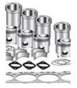
发动机大修包
|
型号
|
数量
|
描述
|
|
TR114082
|
6
|
连杆衬套 PT 41 mm
|
|
TR119874
|
1
|
凸轮轴衬套
|
|
TR501124
|
12
|
连杆螺钉
|
|
TRE31617
|
12
|
气门密封 STEM LITER ENG
|
|
TRE44574
|
1
|
前油封
|
|
TRE505515
|
1
|
后油封
|
|
TRE532631
|
1
|
大修包
|
|
TRE536083
|
6
|
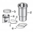
活塞缸套四配套,包括活塞,活塞环,活塞销,缸套,卡簧,阻水圈 (RE527039) 2V
|
|
TRE65165
|
6
|
主轴瓦(标准)
|
|
TRE65168
|
1
|
止推瓦(标准)
|
|
TRE65908
|
6
|
连杆瓦(标准
|
发动机内部修理套件
|
型号
|
数量
|
描述
|
|
TR501124
|
12
|
连杆螺钉
|
|
TR97344
|
1
|
GASKET, OIL PAN 6 CYL
|
|
TRE31617
|
12
|
气门密封 STEM LITER ENG
|
|
TRE532841
|
1
|
GASKET, HEAD SET PT
|
|
TRE536083
|
6
|
活塞缸套四配套,包括活塞,活塞环,活塞销,缸套,卡簧,阻水圈 (RE527039)
|
|
TRE65165
|
6
|
主轴瓦(标准)
|
|
TRE65168
|
1
|
止推瓦(标准)
|
|
TRE65908
|
6
|
连杆瓦(标准
|
约翰迪尔 6068T/H 6.8T/H 活塞(米)RE515037 排放 2 & 3
|
|
|
发动机和设备型号
|
孔径:
4.19 in 106.5 mm
销径 Ø:
1.6250 in (+/- .0002) = 41mm
|
|
|
ventilator assembly-to-rocker arm cover cap screws to specifications. specification crankcase vent baffle-to-rocker arm cover cap screws—torque . 15 n?m (11 lb-ft) (133 lb-in.) 6. install ventilator outlet tube onto elbow attached to rocker arm cover. ctm100 (20mar01) 02-020-2 powertech 10.5 l & 12.5 l diesel engines 032001 pn=74 cylinder head&valves 02 020 3 rg,rg34710,62 –19–30sep97–1/1 replace rocker arm cover gasket rg8784 –un–10dec97 replacing rocker arm cover gasket a—gasket double lips 1. remove rocker arm cover. (see remove and install rocker arm cover earlier in this group.) 2. remove existing gasket from cover&discard. clean gasket groove as needed. 3. position new gasket at two front corners of cover with double lips (a) of gasket facing up. important: do not stretch gasket while seating in groove of cover. 4. seat gasket on front side of cover&proceed around entire cover gasket groove using a deep-well socket. 5. re-seat gasket again (especially in corners) after entire gasket is installed in groove. ctm100 (20mar01) 02-020-3 powertech 10.5 l & 12.5 l diesel engines 032001 pn=75 cylinder head&valves 02 020 4 rg,rg34710,63 –19–16oct00–1/6 check&adjust valve assembly clearances&injector preload rg8228a –un–05dec97 jdg971 timing pin in camshaft rg8227d –un–05dec97 jdg971 timing pin in crankshaft rg11165 –un–30oct00 camshaft timing slot a—jdg971 timing pin b—jdg820 flywheel turning tool c—jdg971 timing pin d—single timing slot e—double timing slot rocker arm assembly adjustments consist of intake and exhaust valve clearance (lash)&electronic unit injector preload adjustment. caution: to prevent accidental starting of engine while performing rocker arm adjustment, always disconnect negative (—) battery terminal. important: all rocker arm assembly adjustments must be performed with engine cold. 1. remove rocker arm cover. (see remove and install rocker arm cover earlier in this group.) 2. remove plug from cylinder block&install jdg820 flywheel turning tool (b). 3. remove threaded plug from timing hole below oil cooler&filter housing assembly. important: timing pin must be installed in slot of camshaft first, then install second timing pin in crankshaft slot by carefully rocking flywheel back and forth. 4. rotate engine flywheel in running direction (counterclockwise as viewed from rear) until jdg971 timing pin (a) engages single timing slot (d) in camshaft. the proper timing slot can be found by viewing camshaft timing lobe through camshaft timing pin bore while rotating engine. the double timing slot (e) will be at approximately 11 o’clock (viewed from rear of engine) when pin is installed in slot (d).this ensures that engine is locked at tdc of no. 1 cylinder’s compression stroke. intake&exhaust rocker arms on no. 1 cylinder should be loose. ctm100 (20mar01) 02-020-4 powertech 10.5 l & 12.5 l diesel engines 032001 pn=76 continued on next page cylinder head&valves 02 020 5 rg,rg34710,63 –19–16oct00–2/6 important: do not insert timing pin full depth into cylinder block crankshaft timing hole when rotating engine flywheel until double slot on camshaft timing lobe is at approximately 11 o’clock (viewed from rear of engine) to avoid crankshaft counterweight bending timing pin. 5. slightly move engine flywheel back&forth with turning tool until a second jdg971 timing pin (c) can be installed in slot in crankshaft. this ensures that camshaft&crankshaft are in sync (properly timed). if timing pin does not enter crankshaft timing slot, crankshaft is not properly timed with camshaft. crankshaft must be timed to camshaft. (see check and adjust camshaft-to-crankshaft timing in group 050.) continued on next page ctm100 (20mar01) 02-020-5 powertech 10.5 l & 12.5 l diesel engines 032001 pn=77 cylinder head&valves 02 020 6 rg,rg34710,63 –19–16oct00–3/6 rg8773 –un–19may98 rocker arm assembly identification rg8232 –un–05dec97 adjusting valve lash/clearance b—valve stem tip 6. check&adjust (as needed) valve stem-to-bridge clearance (lash) on intake valves nos. 1, 2,&4, and exhaust valves nos. 1, 3,&5 (shaded locations). adjust preload on electronic unit injectors nos. 3, 5, and 6 (shaded locations). valve clearance is adjusted using jdg1333 feeler gauge set/equivalent 1/4 inch (6.0 mm) wide automotive ignition point-type feeler gauge installed at the joint between the valve bridge&valve stem tip (b) that is near the exhaust (right) side of engine. loosen lock nuts, set clearance with adjusting screw and tighten lock nut to specified torque while holding adjusting screw stationary. valve stem-to-bridge clearance (engine cold)—specification intake valve—clearance 0.58 ± 0.05 mm (0.023 ± 0.002 in.) exhaust valve—clearance 1.08 ± 0.05 mm (0.043 ± 0.002 in.) . 7. tighten intake&exhaust valve adjusting screw lock nuts to specifications. specification intake&exhaust valve adjusting screw lock nuts— torque . 50 n?m (37 lb-ft) continued on next page ctm100 (20mar01) 02-020-6 powertech 10.5 l & 12.5 l diesel engines 032001 pn=78 cylinder head&valves 02 020 7 rg,rg34710,63 –19–16oct00–4/6 8. set electronic unit injector preload by turning the eui rocker arm adjusting screw in until there is zero clearance between the rocker arm roller&camshaft lobe. next, turn the adjusting screw in an additional one-half turn (180°). hold adjusting screw stationary while tightening lock nut to specified torque. tighten eui adjusting screw lock nuts to specifications. specification electronic unit injector—preload 0.00 mm (in.) clearance plus 1/2 turn in (180°) . electronic unit injector adjusting screw lock nuts—torque 65 n?m (48 lb-ft) continued on next page ctm100 (20mar01) 02-020-7 powertech 10.5 l & 12.5 l diesel engines 032001 pn=79 cylinder head&valves 02 020 8 rg,rg34710,63 –19–16oct00–5/6 rg8774 –un–19may98 rocker arm assembly identification rg8229 –un–05dec97 locking engine at no.6 tdc a—flywheel reference mark b—timing pin 9. reference mark flywheel (a) as shown with engine locked at no.1 tdc compression stroke. important: do not insert timing pin full depth into cylinder block when rotating engine flywheel until reference mark is within a few degrees of a full crankshaft revolution to eliminate possibility of crankshaft counterweight bending timing pin. 10. remove both timing pins&rotate engine flywheel one full revolution (360°) until timing pin (b) enters slot in crankshaft again. engine will now be locked at no. 6 tdc compression stroke. 11. check&adjust, as needed, valve clearance (lash) on intake valves nos. 3, 5,&6&exhaust valves nos. 2, 4,&6 (shaded locations). adjust preload on injectors nos. 1, 2,&4 (shaded locations). 12. tighten intake&exhaust valve adjusting screw lock nuts to specifications. specification intake&exhaust valve adjusting screw lock nuts— torque . 50 n?m (37 lb-ft) tighten eui adjusting screw lock nuts to specifications. specification electronic unit injector adjusting screw lock nuts—torque 65 n?m (48 lb-ft) ctm100 (20mar01) 02-020-8 powertech 10.5 l & 12.5 l diesel engines 032001 pn=80 continued on next page cylinder head&valves 02 020 9 rg,rg34710,63 –19–16oct00–6/6 rg9743 –un–04dec98 inspect valves rg9626a –un–04dec98 adjusting screws a—valve bridges b—valve stems c—push tubes d—adjusting screws important: thoroughly inspect all intake and exhaust valve bridges (a) for proper seating on valve stems (b) from both sides of engine. also, be sure that push tubes (c) are properly seated in top of valve bridge. use a flashlight&carefully check each bridge (for proper seating on valve stems) from both sides of the engine, by lifting up on each bridge to verify proper seating. valve bridges that are not pr0perly seated on valve stems will result in major engine valve train failure. 13. check that all intake rocker arm adjusting screws (d) have approximately the same number of threads visible above lock nut. normally flush to maximum of two threads. if the number of threads above lock nut at any location is visually different, verify bridge seating and readjust valve clearance to ensure everything is within specification at this location. 14. install plug in timing pin hole below oil cooler and tighten to specifications. specification timing pin plug (below oil cooler)—torque 33 n?m (24 lb-ft) ctm100 (20mar01) 02-020-9 powertech 10.5 l & 12.5 l diesel engines 032001 pn=81 cylinder head&valves 02 020 10 rg,rg34710,64 –19–21dec00–1/2 remove rocker arm assembly rg8262b –un–06dec97 removing valve bridge&push tubes rg8459a –un–21jul99 removing rocker arm assembly with jdg970a a—rocker arm shaft oil tubes (dual rail fuel system only) b—rocker arm lifting fixture c—push tubes d—valve bridges caution: after operating engine, allow exhaust system to cool before servicing engine. 1. remove rocker arm cover. 2. lock camshaft&crankshaft at tdc of no.1 cylinder’s compression stroke. 3. remove electronic unit injector wiring harness from rocker arm shaft clamps. important: always loosen all intake, exhaust and eui rocker arm adjusting screws before removal/installation of rocker arm assembly to relieve pressure. this allows for a more uniform rocker arm cap screw clamp load&reduces the possibility of damage to valve train components. remove push tubes&valve bridges immediately after relieving rocker arm pressure. push tubes can fall into oil drain opening of cylinder head causing oil pan removal to retrieve tubes. 4. loosen eui, intake,&exhaust valve rocker arm adjusting screw lock nut&relieve pressure at all locations. 5. remove push tubes (c)&valve bridges (d) from all valve stems. 6. remove two rocker arm shaft oil tubes (a) (dual rail system only). remove rocker arm shaft hold-down clamps. important: rocker arm shaft hold-down clamp cap screws can not be reused. use new cap screws for reassembly. 7. install shaft clamp cap screw in end hole of each rocker arm shaft so that rocker arms do not slide off shaft when lifted. ctm100 (20mar01) 02-020-10 powertech 10.5 l & 12.5 l diesel engines 032001 pn=82 continued on next page cylinder head&valves 02 020 11 rg,rg34710,64 –19–21dec00–2/2 8. depress actuator (ball) pins&install jdg970a rocker arm lifting fixture (b) into rocker arm shaft cap screw holes as shown. replace pins to seat ball locks. 9. remove both front&rear rocker arm&shaft assemblies using jdg970a rocker arm lifting fixture. 10. discard rocker arm shaft hold-down clamp cap screws. ctm100 (20mar01) 02-020-11 powertech 10.5 l & 12.5 l diesel engines 032001 pn=83 cylinder head&valves 02 020 12 rg,rg34710,65 –19–13aug99–1/5 remove cylinder head rg8187a –un–05dec97 removing turbocharger&exhaust manifold a—turbocharger b—exhaust manifold c—thermostat housing/water manifold on some applications, it may be necessary to remove engine from machine to service cylinder head. refer to your machine technical manual for engine removal procedure. caution: after operating engine, allow exhaust system to cool before servicing engine. do not drain coolant until the coolant is below operating temperature. only remove radiator filler cap when cool enough to touch with bare hands. slowly loosen cap to first stop to relieve pressure before removing completely. 1. drain all oil&coolant. 2. remove intake manifold (6105h&6125h engines). (see remove, inspect&install intake manifold in group 080.) 3. remove turbocharger (a). (see remove turbocharger in group 080.) 4. remove exhaust manifold (b). (see remove, inspect&install exhaust manifold in group 080.) 5. on 6105a&6125a engines, remove aftercooler assembly. (see remove&install aftercooler assembly in group 080.) 6. remove thermostat housing/water manifold (c). (see remove&install thermostat housing in group 070.) 7. remove rocker arm assembly. (see remove and install rocker arm assembly, earlier in this group). 8. remove electronic unit injectors&wiring harness. refer to the appropriate fuel system repair manual. lucas ecu controlled fuel systems: ctm100 (20mar01) 02-020-12 powertech 10.5 l & 12.5 l diesel engines 032001 pn=84 continued on next page cylinder head&valves 02 020 13 rg,rg34710,65 –19–13aug99–2/5 ? see remove&install electronic unit injectors in ctm115, section 02, group 090. john deere level 6 ecu controlled fuel systems: ? see remove&install electronic unit injectors in ctm188, section 02, group 090 (dual rail fuel systems). ? see remove&install electronic unit injectors in ctm188, section 02, group 091 (single rail fuel systems). 9. remove fan drive hub&camshaft gear access cover. continued on next page ctm100 (20mar01) 02-020-13 powertech 10.5 l & 12.5 l diesel engines 032001 pn=85 cylinder head&valves 02 020 14 rg,rg34710,65 –19–13aug99–3/5 rg8251a –un–06dec97 removing camshaft gear rg8264b –un–06dec97 removing supply pump&fuel manifold (early engine shown) rg8544b –un–10dec97 dfrg4 camshaft locking tool a—gear retaining washer b—camshaft gear c—fuel manifold d—fuel supply pump e—dfrg4 camshaft locking tool 10. remove six cap screws securing camshaft gear retaining washer (a)&remove camshaft gear (b). note: later engines with single rail fuel systems do not have a fuel manifold. return fuel line is connected to port of single rail in back of cylinder head. inlet line&port are on left side of head up by no.1 cylinder. 11. remove fuel manifold block (c) on engines with dual rail systems,/disconnect fuel inlet&return lines on single rail systems. refer to the appropriate fuel system repair manual. lucas ecu controlled fuel systems: ? see remove&install fuel manifold in ctm115, section 02, group 090. john deere level 6 ecu controlled fuel systems: ? see remove&install fuel manifold in ctm188, section 02, group 090. 12. remove fuel supply pump. refer to the appropriate fuel system repair manual. lucas ecu controlled fuel systems: ? see remove&install fuel supply pump in ctm115, section 02, group 090. john deere level 6 ecu controlled fuel systems: ? see remove&install fuel supply pump in ctm188, section 02, group 090 (dual rail fuel systems). ? see remove&install fuel supply pump in ctm188, section 02, group 091 (single rail fuel systems). continued on next page ctm100 (20mar01) 02-020-14 powertech 10.5 l & 12.5 l diesel engines 032001 pn=86 cylinder head&valves 02 020 15 rg,rg34710,65 –19–13aug99–4/5 note: cylinder head can be removed without removing camshaft. important: if cylinder head is removed with camshaft installed, secure camshaft in bushings with dfrg4 camshaft locking tool (e) so that camshaft journals&bushings are not damaged by camshaft sliding out of bushings. (see dfrg4-camshaft locking tool in section 05, group 190 for details on this dealer fabricated tool.) camshaft position sen must be removed from air intake side of cylinder head when removing/installing camshaft to prevent camshaft binding on sen . 13. remove camshaft front thrust ring. remove camshaft position sen &remove camshaft if desired (see remove&install camshaft in group 050). continued on next page ctm100 (20mar01) 02-020-15 powertech 10.5 l & 12.5 l diesel engines 032001 pn=87 cylinder head&valves 02 020 16 rg,rg34710,65 –19–13aug99–5/5 rg8285 –un–21may98 removing cylinder head note: if removing head with camshaft installed, camshaft will have to be rotated to remove two of the cylinder head cap screws. 14. remove 26 cylinder head cap screws with washers and discard. important: do not use screwdrivers/prybars between cylinder block&head to loosen gasket seal. screwdrivers and prybars can damage head&block gasket surfaces. 15. carefully lift cylinder head from block using an overhead hoist/floor crane. place head on a clean, flat surface. 16. remove cylinder head gasket. inspect gasket for any manufacturing imperfections. inspect head, gasket, and check for possible oil, coolant,/combustion chamber leakage. note: do not rotate engine crankshaft with cylinder head removed unless all cylinder liners are secured with cap screws&large, flat washers. (see remove pistons&connecting rods in group 030.) ctm100 (20mar01) 02-020-16 powertech 10.5 l & 12.5 l diesel engines 032001 pn=88 cylinder head&valves 02 020 17 rg,rg34710,69 –19–01nov00–1/2 diagnosing head gasket joint failures益阳强鹿活塞环RE515941价格一级代理,嘉峪关约翰迪尔连杆瓦RE65908多少钱,金昌美国JohnDeere柴滤RE532952厂家批发,临汾美国JohnDeere发动机修理包RE527549一级代理,莱芜约翰迪尔强鹿柴油机R98062进气门哪里买,菏泽约翰迪尔强鹿4045柴油机配件活塞环厂家批发,果洛约翰迪尔强鹿4045柴油机左平衡轴TRE500449诚信推荐,鸡西约翰迪尔6068柴油机止推轴承瓦哪家好,温州约翰迪尔R97341机油底壳垫片代理商,怒江强鹿6090柴油发动机曲轴公司,郴州约翰迪尔温度传感器RE522823市场报价,新竹JohnDeere发动机大修包RE526727公司,泉州强鹿-约翰迪尔发动4039df008配件哪家买,吐鲁番johndeere约翰迪尔强鹿输油泵批发商, rg8430 –un–22may98 cylinder head gasket sealing area a—combustion sealing areas b—coolant sealing areas c—cylinder head cap screws head gasket failures generally fall into three categories: ? combustion seal leakage. ? coolant seal leakage. ? oil seal leakage. combustion seal leakage failures occur when combustion gases escape between cylinder head&head gasket combustion flange,/between combustion flange and cylinder liner. leaking combustion gases may vent to an adjacent cylinder, to a coolant/oil passage, or externally. coolant/oil seal failures occur when oil/coolant escapes between cylinder head&gasket body, or between cylinder block&gasket body. the oil or coolant may leak to an adjacent coolant/oil passage, or externally. follow these diagnostic procedures when a head gasket joint failure occurs/is suspected: 1. before starting/disassembling engine, conduct a visual inspection of machine,?e any of the following: ? oil/coolant in head gasket seam,/on adjacent surfaces, especially right rear corner of gasket joint. ? displacement of gasket from normal position. ? discoloration/soot from combustion gas leakage. ? leaking radiator, overflow tank,/hoses. ? leaking coolant from coolant pump weep hole. ? damaged/incorrect radiator, fan,/shroud. ? obstructed air flow/coolant flow. ? worn/slipping belts. ? damaged/incorrect pressure cap. ? presence of oil in coolant. ? low coolant levels/improper coolant. ? unusually high/low oil levels. ? oil degradation, dilution,/contamination. ? correctly specified electronic unit injectors. ? indications of fuel delivery/gear train not properly timed. ? unburned fuel/coolant in exhaust system. ctm100 (20mar01) 02-020-17 powertech 10.5 l & 12.5 l diesel engines 032001 pn=89 continued on next page cylinder head&valves 02 020 18 rg,rg34710,69 –19–01nov00–2/2 2. obtain coolant&oil samples for further analysis. 3. start&warm up engine if it can be safely operated. examine all potential leakage areas again as outlined previously. using appropriate test&measurement equipment, check for the following: ? white smoke, excessive raw fuel,/moisture in exhaust system. ? rough, irregular exhaust sound,/misfiring. ? air bubbles, gas entrainment in radiator/overflow tank. ? loss of coolant from overflow. ? excessive cooling system pressure. ? coolant overheating. ? low coolant flow. ? loss of cab heating (air lock). 4. shut engine down. recheck crankcase, radiator, and overflow tank for any significant differences in fluid levels, viscosity,/appearance. 5. compare your observations from above steps with the appropriate diagnostic procedures in section 04, group 150. if diagnostic evaluations&observations provide conclusive evidence of combustion gas, coolant,/oil leakage from head gasket joint, the cylinder head must be removed for inspection&repair of gasket joint components. ctm100 (20mar01) 02-020-18 powertech 10.5 l & 12.5 l diesel engines 032001 pn=90 cylinder head&valves 02 020 19 rg,rg34710,70 –19–30sep97–1/2 head gasket inspection&repair sequence rg8429 –un–19may98 cylinder head gasket inspection a—combustion seals b—gasket body c—front of engine (flanges) the following inspection procedures are recommended whenever a head gasket joint failure occurs/when joint disassembly takes place. 1. review historical data relating to machine operation, maintenance&repair, along with diagnostic observations. note all areas requiring further inspection&analysis. 2. remove rocker arm cover&check for presence of coolant in the oil. 3. record head cap screw torques prior to removal. upon removal, check cap screw length differences. 4. remove cylinder head using appropriate lifting devices to prevent handling damage to head gasket. (see remove cylinder head in this group.) 5. observe surfaces of removed head gasket. examine combustion seals (a) for the following: ? flange severed/expanded/cracked/deformed. ? adjacent body area burned/eroded. ? fire ring severed/displaced/missing. ? flange sealing pattern eccentric/contains voids. ? discoloration of flange&adjacent body areas. ? flange surfaces rough/abraided/channelled. examine gasket body (b) for the following: ? combustion gas erosion paths/soot deposits originating at combustion seals. ? extreme discoloration/hardening/embrittlement in localized areas. ? oil/coolant paths from port areas. ? localized areas of low compression. 6. before cleaning components, inspect head, block, and liners for evidence of combustion gas&fluid leakage. inspect cylinders&valve ports for unusual deposits. 7. clean cylinder block. (see inspect&clean cylinder block in group 030.) clean cylinder head. (see clean&inspect cylinder head in this group.) clean liners. (see clean cylinder liners in group 030.) 8. proceed with the following dimensional checks and visual inspections: ? cylinder head (this group) – check surface flatness/finish. – inspect for surface damage. – check cylinder head thickness, if resurfacing. ? cylinder block&liners (assembled and clamped) (group 030) ctm100 (20mar01) 02-020-19 powertech 10.5 l & 12.5 l diesel engines 032001 pn=91 continued on next page cylinder head&valves 02 020 20 rg,rg34710,70 –19–30sep97–2/2 – check liner standout at four places on each liner. – check liner standout difference between cylinders. ? cylinder block (group 030) – check surface flatness/finish. – inspect for surface damage. – check liner counterbore depth (if liner is removed). – check top deck to crankshaft centerline dimension. – inspect cap screw bosses; must be clean/intact. ? cylinder liner (group 030) – check liner flange flatness/finish. – check liner flange thickness (if liner is removed). – inspect flange for damage. ? cylinder head cap screws (this group) – inspect condition of threads. – check length. 9. when inspections&measurements have been completed, determine most probable causes of joint failure. make all necessary repairs to joint components, cooling system,&fuel injection system. 10. reassemble the engine according to procedures and specifications in the appropriate repair groups of this manual. ctm100 (20mar01) 02-020-20 powertech 10.5 l & 12.5 l diesel engines 032001 pn=92 cylinder head&valves 02 020 21 rg,rg34710,71 –19–30sep97–1/1 disassemble&inspect rocker arms and shaft assembly rg8395 –un–21may98 measure rocker arm shaft rg8392 –un–21may98 measure rocker arm bushing rg8390 –un–21may98 measure rocker arm roller 1. remove rocker arms from shaft&identify for installation in same position as removed. 2. inspect rocker arm shaft for scoring&excess wear at rocker arm contact points. roll on a flat surface and check for bends/distortion. 3. check rocker arm adjusting screws&lock nuts for thread damage. 4. check valve bridges&push tubes for contact wear. 5. clean all parts with clean solvent. dry with compressed air. 6. measure rocker arm shaft od&rocker arm bushing id. compare measurements with specifications below. 7. inspect rocker arm roller for uneven wear. measure roller od&compare with specifications below. specification rocker arm bushing—id 38.064 ± 0.013 mm (1.4986 ± 0.0005 in.) . rocker arm shaft—od 38.000 ± 0.013 mm (1.4961 ± 0.0005 in.) rocker arm shaft-to-bushing— oil clearance 0.064 ± 0.026 mm (0.0025 ± 0.0010 in.) rocker arm shaft intake and exhaust roller—od 39.995—40.045 mm (1.5746—1.5766 in.) rocker arm shaft unit injector roller—od 37.995—38.045 mm (1.4959—1.4978 in.) replace parts as necessary. ctm100 (20mar01) 02-020-21 powertech 10.5 l & 12.5 l diesel engines 032001 pn=93 cylinder head&valves 02 020 22 rg,rg34710,72 –19–30sep97–1/1 preliminary cylinder head&valve checks make preliminary inspection of cylinder head&valve assembly during disassembly. look for the following conditions: sticking valves: ? carbon deposits on valve stem. ? worn valve guides. ? scored valve stems. ? warped valve stems. ? misaligned/broken valve springs. ? worn/distorted valve seats. ? insufficient lubrication. warped, worn,/distorted valve guides: ? lack of lubrication. ? cylinder head distortion. ? excessive heat. ? unevenly tightened cylinder head cap screws. distorted cylinder head&gasket leakage: ? loss of cylinder head cap screw torque. ? broken cylinder head cap screw. ? overheating from low coolant level operation. ? insufficient liner standout. ? coolant leakage into cylinder causing hydraulic failure of gasket. ? leaking aftercooler. ? cracked cylinder head. ? cracked cylinder liner. ? damaged/incorrect gasket. ? overpowering/overfueling. ? damaged cylinder head/block surfaces. ? improper surface finish on cylinder head. ? improperly tightened cylinder head cap screws or faulty gasket installation (misaligned). worn/broken valve seats: ? misaligned valves. ? distorted cylinder head. ? carbon deposits on seats due to incomplete combustion. ? valve spring tension too weak. ? excessive heat. ? improper valve clearance. ? improper valve timing. ? incorrect valve/seat installed. burned, pitted, worn,/broken valves: ? worn/distorted valve seats. ? loose valve seats. ? worn valve guides. ? insufficient cooling. ? cocked/broken valve springs. ? improper engine operation. ? improper valve train timing. ? faulty valve rotators. ?昌都约翰迪尔发动机柱塞诚信推荐,长沙强鹿R115250皮带轮的价格,抚州强鹿油水分离器滤芯re62418的价格,扬州JohnDeere气门弹簧R502187多少钱,娄底约翰迪尔油泵RE66153找哪家,清远强鹿6068柴油机连杆螺丝找哪家,温州约翰迪尔4045柴油机连杆RE500608供货商,阜新约翰迪尔连杆瓦R116081批发商,晋城强鹿6090柴油发动机气门锁夹哪里买,兰州约翰迪尔E140LC挖掘机发动机配件价格,沈阳约翰迪尔4039DF008水泵总成AR97708供应商,兰州约翰迪尔柴滤RE504836找哪家,张家界强鹿柴油滤芯RE60021厂家价格,无堂划分域约翰迪尔齿环R28811价格行情, warped/distorted valve stems. ? “stretched” valves due to excessive spring tension. ? warped cylinder head. ? carbon build-up on valve seats. ? rocker arm failure. ? incorrect valve/seat installed. ? incorrect piston-to-valve clearance. improper valve clearance: ? inefficient use of fuel. ? engine starts harder. ? maximum engine power will not be achieved. ? shorter service life of valve train. ? greater chance for engine to overheat. excessive valve recession: ? worn valve seats. ? bent valves. ? debris passed through valve train. ctm100 (20mar01) 02-020-22 powertech 10.5 l & 12.5 l diesel engines 032001 pn=94 cylinder head&valves 02 020 23 rg,rg34710,73 –19–13aug99–1/1 assemble rocker arms&shaft assembly rg8460 –un–21may98 rocker arm&shaft assembly rg8304 –un–06dec97 lifting rocker arm assembly a—jdg970a rocker arm assembly lifting fixture b—cap screw c—cap screw 1. make sure that rocker arm shaft end plugs are firmly seated in each shaft end bore. 2. assemble parts on rocker arm shaft in reverse sequence as removed. 3. install cap screws (b)&(c) in holes at each end of rocker arm shaft to keep rocker arms from sliding off shaft during installation. 4. install jdg970a rocker arm lifting fixture (a) onto rocker arm&shaft assembly. rg,rg34710,74 –19–03nov99–1/1 check valve height in relation to head surface (valve recess) rg8330a –un–09dec97 measure valve recess a—height gauge b—dial indicator 1. thoroughly clean all gasket material from cylinder head combustion face. 2. measure&record valve recess using jdg451 (english)/kjd10123 (metric) height gauge (a) along with d17526ci (english, in.)/d17527ci dial indicator (metric) (b). measurements must be made a maximum of 3.0 mm (0.12 in.) in from edge of valve head. specification intake&exhaust valves— recess . 1.85—2.35 mm (0.073—0.093 in.) install new valves, inserts,/grind existing valves and inserts (as necessary) to obtain specified valve recess. ctm100 (20mar01) 02-020-23 powertech 10.5 l & 12.5 l diesel engines 032001 pn=95 cylinder head&valves 02 020 24 rg,rg34710,75 –19–30sep97–1/1 remove valve assembly rg8305 –un–06dec97 removing valve springs rg8306b –un–06dec97 removing valve stem seals a—jdg982 valve spring compres b—valve springs c—valve rotators d—valve retainer locks e—valve stem seals note: a small magnet may be used to aid removal of valve retainer locks (d). 1. place cylinder head on a clean flat surface with combustion face down. 2. using jdg982 valve spring compres (a), compress valve spring far enough to remove retainer locks as shown. 3. release spring tension, remove valve rotator (c) and valve spring (b). 4. remove valve stem seals (e) from valve guide tower. 5. lay cylinder head on air intake side using a 1016 x 51 x 102 mm (40 x 2.0 x 4.0 in.) block of wood. 6. remove valves&identify for assembly in same location. ctm100 (20mar01) 02-020-24 powertech 10.5 l & 12.5 l diesel engines 032001 pn=96 cylinder head&valves 02 020 25 rg,rg34710,76 –19–13aug99–1/1 inspect&measure valve springs rg2732 –un–04dec97 valve spring rg7427 –un–21may98 measuring valve spring compression important: replacement valve springs (r133891) have higher working loads than older springs (r116585). newer valve springs (r133891) have two green paint stripes for identification. valve springs must be replaced in sets of two with new rotators. do not intermix springs across valve bridges. 1. inspect valve springs for alignment, wear,&damage. 2. using d01168aa spring compression tester, check valve spring tension. compressed height must be within specification given below. specification intake&exhaust valve springs (all)1—height at 0 n (0 lb-force) free length . 67.9—72.1 mm (2.67—2.84 in.) intake&exhaust valve springs (r116585)—height at 352—396 n (79—89 lb-force) (valve closed) . 59.4 mm (2.34 in.) intake&exhaust valve springs (r116585)—height at 845—935 n (190-210 lb-force) (valve open) 45.5 mm (1.79 in.) intake&exhaust valve springs (r133891)—height at 527—593 n (118—133 lb-force) (valve closed) . 59.4 mm (2.34 in.) intake&exhaust valve springs (r133891)—height at 1187— 1313 n (267—295 lb-force) (valve open) 46.4 mm (1.83 in.) 1 free length of springs may vary slightly between springs. ctm100 (20mar01) 02-020-25 powertech 10.5 l & 12.5 l diesel engines 032001 pn=97 cylinder head&valves 02 020 26 rg,rg34710,77 –19–30sep97–1/1 inspect valve rotators rg8323 –un–21may98 inspecting valve rotator valve rotators cannot be repaired. replace valve rotators when valves are replaced/reground. ensure that valve rotators turn freely in both directions. replace if defective. ctm100 (20mar01) 02-020-26 powertech 10.5 l & 12.5 l diesel engines 032001 pn=98 cylinder head&valves 02 020 27 rg,rg34710,78 –19–13aug99–1/1 clean, inspect,&measure valves rg8322 –un–21may98 measuring valve stem rg4234 –un–05dec97 measuring valve face runout 1. hold each valve firmly against a soft brass/copper wire wheel on a bench grinder. important: any carbon left on the stem will affect alignment in valve refacer. do not use a wire wheel on plated portion of valve stem. polish the valve stem with steel wool/crocus cloth to remove any scratch marks left by the wire brush. 2. make sure all carbon is removed from valve head, face,&unplated portion of stem. 3. inspect valve face, stem, tip,&retainer lock groove. 4. measure valve stem od record measurements and compare with valve guide id. (see measure valve guide id, later in this group.) specification intake&exhaust valve stems—od 8.999 ± 0.013 mm (0.3543 ± 0.0005 in.) . 5. using a valve inspection center, determine if valves are out of round, bent,/warped. specification intake&exhaust valve face1—maximum runout . 0.038 mm (0.0015 in.) 6. measure valve head od. specification intake&exhaust valve head— od 46.35—46.61 mm (1.825—1.835 in.) . 1maximum runout measured at 44 mm (1.73 in.) diameter. ctm100 (20mar01) 02-020-27 powertech 10.5 l & 12.5 l diesel engines 032001 pn=99 cylinder head&valves 02 020 28 rg,rg34710,79 –19–30sep97–1/1 grind valves rg4755 –un–31oct97 valve face angle a—valve face angle reface serviceable valves to specified angle (a). face angle on intake&exhaust valves is as follows: specification intake&exhaust valve face— angle . 29.25° ± 0.25° important: do not nick valve head-to-stem radius when grinding valves. a nick could cause the valve to break. break all sharp edges after grinding. ctm100 (20mar01) 02-020-28 powertech 10.5 l & 12.5 l diesel engines 032001 pn=100 cylinder head&valves 02 020 29 rg,rg34710,80 –19–13aug99–1/2 clean&inspect cylinder head rg8266 –un–06dec97 fuel rail a—supply rails (dual rail system shown) important: do not use scouring pads/wire brush to clean gasket sealing surface (combustion face). doing so may affect sealing ability of gasket joint. do not “hot tank” clean cylinder head unless all plugs&valve guides are removed for replacement. hot tank solution will destroy lubricating properties of valve guides. 1. inspect combustion face for evidence of physical damage, oil/coolant leakage,/gasket failure prior to cleaning the cylinder head. repair/replace cylinder head if there is evidence of physical damage such as cracking, abrasion, distortion,/valve seat “torching.” inspect all cylinder head passages for restrictions. 2. inspect around injector sleeve for evidence of fuel or coolant leakage. 3. scrape gasket material, oil, carbon,&rust from head. use a powered brass/copper (soft) wire brush to clean sealing surfaces. do not use a steel wire brush. 4. clean valve guides using a plastic brush. important: during engine repair/overhaul, cleanliness of fuel supply rail(s) (a) is extremely important due to fuel flow through passages. think of the fuel rails as internal passages of an injection pump; therefore, same cleanliness must be maintained. 5. remove fuel rail expansion plug in front of cylinder head&thoroughly clean fuel rail passage using a rifle-type cleaner. all debris must be removed from fuel rail. 6. dry with compressed air&blow out all passages. ctm100 (20mar01) 02-020-29 powertech 10.5 l & 12.5 l diesel engines 032001 pn=101 continued on next page cylinder head&valves 02 020 30 rg,rg34710,80 –19–13aug99–2/2 7. final dry fuel rail passages with clean lint-free cloth and rifle cleaner. 8. coat new expansion plug with loctite? 277 plastic gasket&install in front face of head. loctite is a registered trademark of loctite corp. rg,rg34710,81 –19–30sep97–1/1 check cylinder head flatness rg8309 –un–21may98 measuring cylinder head flatness check cylinder head flatness using d05012st precision straightedge&feeler gauge. check lengthwise, crosswise,&diagonally in several places. specification cylinder head—maximum acceptable out-of-flat for entire length of head . 0.10 mm (0.004 in.) maximum acceptable out-of-flat for every 305 mm (12.0 in.) . 0.025 mm (0.0009 in.) if out-of-flat exceeds specifications, the cylinder head must be resurfaced/replaced. (see measure cylinder head thickness later in this group.) ctm100 (20mar01) 02-020-30 powertech 10.5 l & 12.5 l diesel engines 032001 pn=102 cylinder head&valves 02 020 31 rg,rg34710,82 –19–30sep97–1/1 measure cylinder head thickness rg8324 –un–21may98 using depth gauge rg8325 –un–21may98 measuring cylinder head thickness measure cylinder head thickness from rocker cavity-to-combustion face. if cylinder head thickness is less than wear limit, do not attempt to resurface. install a new cylinder head. if cylinder head thickness is greater than wear limit, a maximum of 0.15 mm (0.006 in.) can be ground from new part dimension for a
KEY PART NO. PART NAME QTY SERIAL NO. F F F REMARKS
1 .. HOLDER NA X X
2 T24210 O-RING 6 X X
3 R76358 O-RING 1 X X
4 14M7272 NUT 3 X X M6
5 12M7006 LOCK WASHER 3 X X 0.236"
6 R67879 GASKET 1 X X
7 R53899 WASHER 1 X X
8 AR77114 CONTROL VALVE 1 X X
9 R53901 WASHER 1 X X
10 R63016 ADAPTER 1 X X
11 R67364 ELBOW FITTING 1 -087549 X X
RE502650 FITTING 1 087550- X X
KEY PART NO. PART NAME QTY SERIAL NO. F F F REMARKS
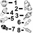
1 RE65265 HAND PRIMER 1 X X (SUB FOR RE48048)
2 R54025 WASHER 1 X X
3 R26448 O-RING 2 X X
4 RE10258 ELBOW FITTING 2 X X (M14 X 5/8 IN.)
5 R67879 GASKET 1 X X
6 RE46375 FUEL PUMP 1 X X (ROBERT BOSCH)
7 51M4238 SEALING RING 1 X X (SUB FOR R93008, THIS APPLICATION)
8 R83490 FITTING 1 X X
KEY PART NO. PART NAME QTY SERIAL NO. F F F REMARKS
1 RE57151 FUEL LINE 1 X X NO. 6
2 RE57150 FUEL LINE 1 X X NO. 5
3 RE57149 FUEL LINE 1 X X NO. 4
4 R71398 SCREW 5 X X
R58186 CLAMP 10 X X
R59305 STRAP 5 X X
R61144 STRAP 5 X X
R74030 CLAMP 1 X X
5 RE57148 FUEL LINE 1 X X NO. 3
6 RE57147 FUEL LINE 1 -081549 X X NO. 2
RE502933 FUEL LINE 1 081550- X X NO. 2
7 RE57146 FUEL LINE 1 -081549 X X NO. 1
RE502932 FUEL LINE 1 081550- X X NO. 1
8 21H1463 CAP SCREW 2 X X 0.190" X 7/8"
R59298 STRAP 1 X X
R61145 STRAP 1 X X
R120184 STRAP 1 X X
R59297 HALF CLAMP 2 X X
9 R59298 STRAP 1 X X
R58186 CLAMP 1 X X
R71212 CLAMP 1 X X
R74804 CLAMP 1 X X
R71398 SCREW 1 X X
R61145 STRAP 1 X X
R120182 STRAP 1 X X
10 21H1463 CAP SCREW 1 X X 0.190" X 7/8"
R59297 HALF CLAMP 2 X X
R59598 GASKET 2 X X
11 RE55662 ABSORBER 1 X X
12 24H1884 WASHER 1 X X 13/32" X 13/16" X 0.120" 13/32" X
13/16" X 0.120", (NLR)
13 19M7166 CAP SCREW 1 X X M10 X 20 M10 X 20
14 RE61593 INJECTION NOZZLE 6 X X (A) (ROBERT BOSCH)
R51603 O-RING 6 X X
15 R84472 WASHER 6 X X 7.360 X 18.160 X 2 MM (0.290" X 0.715"
X 0.079") 7.360 X 18.160 X 2 MM
(0.290" X 0.715" X 0.079")
16 R504057 O-RING 6 087550- X X
17 RE501970 ADAPTER 6 087550- X X
18 R79604 TUBE NUT 6 087550- X X
19 R51937 TUBE NUT 1 X X
20 AR85519 PLUG 1 X X
21 RE500803 FUEL LINE 1 087550- X X
22 R77551 O-RING 6 -087549 X X
23 R87082 FITTING 6 -087549 X X
24 R79604 TUBE NUT 6 -087549 X X
25 R79605 WASHER 6 -087549 X X
26 R79606 TEE FITTING 6 -087549 X X
27 R51936 SEALING WASHER 11 -087549 X X
28 RE15807 FUEL LINE 2 -087549 X X
29 RE15808 FUEL LINE 2 -087549 X X
30 RE36421 FUEL LINE 2 -087549 X X
31 R97061 TEE FITTING 1 -087549 X X
(A) 1 ORANGE DOT
(1) POINT ORANGE
(1) ORANGEFARBENER PUNKT
(1) PUNTO ARANCIONE
(1) PUNTO ANARANJADO
(1) ORANGEFAERGAD PUNKT
KEY PART NO. PART NAME QTY SERIAL NO. F F F REMARKS
1 R60277 SNAP RING 1 X X
2 R375R O-RING 1 X X
3 R60279 NUT 1 X X
4 R60278 SNAP RING 1 X X
5 .. NOZZLE HOLDER 1 X X (SUB RE61593)
6 R83720 WASHER 1 X X 1.02 MM (.0402")
R83721 WASHER 1 X X 1.08 MM (.0425")
R83722 WASHER 1 X X 1.12 MM (.0441")
R83723 WASHER 1 X X 1.18 MM (.0465")
R83724 WASHER 1 X X 1.22 MM (.0480")
R83725 WASHER 1 X X 1.28 MM (.0504")
R83726 WASHER 1 X X 1.30 MM (.0512")
R83727 WASHER 1 X X 1.38 MM (.0543")
R83728 WASHER 1 X X 1.42 MM (.0559")
R83729 WASHER 1 X X 1.48 MM (.0583")
R83730 WASHER 1 X X 1.50 MM (.0591")
R83731 WASHER 1 X X 1.58 MM (.0622")
R83732 WASHER 1 X X 1.60 MM (.0630")
R83733 WASHER 1 X X 1.68 MM (.0661")
R83734 WASHER 1 X X 1.70 MM (.0669")
R83735 WASHER 1 X X 1.78 MM (.0701")
R83736 WASHER 1 X X 1.82 MM (.0717")
R83737 WASHER 1 X X 1.88 MM (.0740")
R83738 WASHER 1 X X 1.90 MM (.0748")
R83739 WASHER 1 X X 1.98 MM (.0780")
7 R108699 SPRING 1 X X
8 R108700 SEAT 1 X X
9 R108701 PLATE 1 X X
10 RE42306 INJECTION NOZZLE 1 X X (7 X .240)
11 R127176 NUT 1 X X
12 R84472 WASHER 1 X X
13 RE61593 INJECTION NOZZLE 6 X X (A) (ROBERT BOSCH)
(A) (1) ORANGE DOT
(1) POINT ORANGE
(1) ORANGEFARBENER PUNKT
(1) PUNTO ARANCIONE
(1) PUNTO ANARANJADO
(1) ORANGEFAERGAD PUNKT
