 English
 Espaol
 Franais
 阿拉伯
阿拉伯 中文(简)
中文(简) Deutsch
 Italiano
 Português
 日本
日本 韩国
韩国 български
 hrvatski
 esky
esky Dansk
Dansk Nederlands
 suomi
suomi Ελληνικ
 印度
印度 norsk
norsk Polski
 Roman
Roman русский
 Svenska
 珀金斯Perkins1206E-E70TTA技术资料,珀金斯Perkins1206E-E70TTA技术资料技术支持中心,珀金斯Perkins1206E-E70TTA技术资料代理商,珀金斯Perkins1206E-E70TTA技术资料销售服务中心,珀金斯Perkins1206E-E70TTA技术资料价格规格资料查询,宁波日昕动力科技有限公司

珀金斯Perkins1206E-E70TTA技术资料
详细描述
Specifications
1206E-E70TTA Industrial Engine
BL (Engine)
This document is printed from SPI². Not for RESALE
![]()
![]()
![]()

Important Safety Information
Most accidents tha t involve produc t op eration, ma intena nc e and repair are caus ed by failure to
ob serve basic safety rules or precautions . An accident can often be avoided by recog nizing pote ntially
ha za rdous situations before an accident oc curs . A person mus t be alert to pote ntial ha za rds. This
person should also ha ve the ne cessary training, skills and tools to perform the se func tions properly.
Improper operation, lubrication, maintenance or repair of this product can be dangerous and
could result in injury or death.
Do not operate or perform any lubrication, maintenance or repair on this product, until you have
read and understood the operation, lubrication, maintenance and repair information.
Sa fety precautions and warning s are provided in this ma nua l and on the produc t. If the se ha za rd
warning s are not he eded, bod ily injury or death could oc cur to you or to othe r persons .
The ha za rds are identified by the “Safety Alert Symb ol” and followed by a “Signa l Word” suc h as
“DANGER”, “WARNING” or “CAUTION”. The Sa fety Alert “WARNING” label is shown below.
The me aning of this safety alert symb ol is as follows:
Attention! Become Alert! Your Safety is Involved.
The me ssage tha t appears und er the warning explains the ha za rd and can be either written or
pictorially presente d.
Op erations tha t ma y caus e produc t dama ge are identified by “NOTICE” labels on the produc t and in
this pub lication.
Perkins cannot anticipate every possible circumstance that might involve a potential hazard. The
warnings in this publication and on the product are, therefore, not all inclusive. If a tool, procedure,
work method or operating technique that is not specifically recommended by Perkins is used,
you must satisfy yourself that it is safe for you and for others. You should also ensure that the
product will not be damaged or be made unsafe by the operation, lubrication, maintenance or
repair procedures that you choose.
The informa tion, specifications , and illustrations in this pub lication are on the basis of informa tion tha t
was available at the time tha t the pub lication was written. The specifications , torque s, pressure s,
me asure me nts , adjustme nts , illustrations , and othe r items can cha ng e at any time. These cha ng es can
affect the service tha t is given to the produc t. Ob tain the comp lete and mos t current informa tion before
you start any job. Pe rkins dealers or Pe rkins distributors ha ve the mos t current informa tion available.
When replacement parts are required for this
product Perkins recommends using Perkins
replacement parts.
Failure to heed this warning can lead to prema-
ture failures, product damage, personal injury or
death.
This document is printed from SPI². Not for RESALE
![]()
![]()
KENR8798-01
3
Table of Contents
Table of Contents
Engine Oil Pressure Sensor ................................. 47
Boost Pressure Sensor ......................................... 48
Atmospheric Pressure Sensor .............................. 48
Inlet Manifold Temperature Sensor ....................... 49
Pressure Sensor (NOx Reduction System) .......... 49
Temperature Sensor (NOx Reduction System) .... 49
Diesel Particulate Filter Temperature and Pressure
Sensor ................................................................. 50
Speed/Timing Sensor .......................................... 51
Electronic Control Module ..................................... 51
Electronic Control Wiring Group (Aftertreatment
Regeneration Device) ......................................... 52
Glow Plugs ........................................................... 52
Air Compressor (Twin Cylinder Compressor) ....... 53
Air Compressor (Single Cylinder) ......................... 54
Specifications Section
Engine Design .....................................................
Fuel Injection Lines ..............................................
Fuel Injection Pump .............................................
Fuel Injectors .......................................................
Fuel Transfer Pump .............................................
Fuel Filter Base (Single Secondary Fuel Filter
Base) ...................................................................
Fuel Filter Base (Twin Secondary Fuel Filter
Base) ...................................................................
Fuel Filter Base (Primary Fuel Filter Base) ...........
Fuel Control Manifold (Aftertreatment Regeneration
Device) ................................................................
Fuel Manifold (Rail) ...............................................
Lifter Group ...........................................................
4
4
5
6
6
7
7
8
Index Section
8
8
9
Index ..................................................................... 55
Rocker Shaft ........................................................ 10
Valve Mechanism Cover ...................................... 11
Cylinder Head Valves ........................................... 11
Cylinder Head ...................................................... 12
Turbocharger (Series Turbochargers) .................. 14
Exhaust Gas Valve (NRS) .................................... 16
Exhaust Sensor and Lines Gp (NRS) ................... 18
Exhaust Cooler (NRS) .......................................... 18
Exhaust Manifold ................................................. 21
Flexible Exhaust Pipe ........................................... 22
Diesel Particulate Filter ......................................... 22
Camshaft ............................................................. 23
Camshaft Bearings .............................................. 24
Engine Oil Filter Base .......................................... 24
Engine Oil Cooler ................................................. 25
Engine Oil Pump .................................................. 25
Engine Oil Pressure ............................................. 26
Engine Oil Pan ..................................................... 27
Crankcase Breather ............................................. 29
Water Temperature Regulator and Housing ......... 29
Water Pump ......................................................... 30
Cylinder Block ...................................................... 30
Crankshaft ........................................................... 31
Crankshaft Seals ................................................. 32
Vibration Damper and Pulley ............................... 33
Connecting Rod Bearing Journal ......................... 33
Main Bearing Journal ............................................ 34
Connecting Rod ................................................... 34
Piston and Rings .................................................. 36
Piston Cooling Jet ................................................. 37
Accessory Drive (SAE “B”) ................................... 37
Accessory Drive ................................................... 38
Front Housing and Covers ................................... 38
Gear Group (Front) ............................................... 39
Flywheel ............................................................... 40
Flywheel Housing ................................................ 41
Belt Tensioner ....................................................... 42
Refrigerant Compressor ....................................... 42
Fan Drive ............................................................. 43
Engine Lifting Bracket ........................................... 43
Alternator ............................................................. 43
Starter Motor ........................................................ 45
Coolant Temperature Sensor ............................... 47
This document is printed from SPI². Not for RESALE
![]()
4
KENR8798-01
Specifications Section
Specifications Section
i04085729
Fuel Injection Lines
i03519906
Engine Design
Contact with high pressure fuel may cause fluid
penetration and burn hazards. High pressure fu-
el spray may cause a fire hazard. Failure to fol-
low these inspection, maintenance and service in-
structions may cause personal injury or death.
Refer to Operation and Maintenance Manual,
“General Hazard Information and High Pressure Fuel
Lines” before adjustments and repairs are performed.
NOTICE
Refer to Systems Operation, Testing and Adjust-
ing, “Cleanliness of Fuel System Components” for
detailed information on the standards of cleanli-
ness that must be observed during ALL work on
the fuel system.
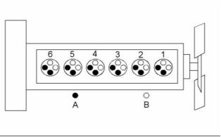
g01284058
Illustration 1
Cylinder and valve location
(A) Exhaust valve
(B) Inlet valve
Ensure that all adjustments and repairs are performed
by authorized personnel that have had the correct
training.
Bore ......................................... 105 mm (4.133 inch)
Stroke ...................................... 135 mm (5.315 inch)
Displacement ................... 7.01 L (427.78 cubic inch)
Cylinder arrangement ..................................... In-line
Type of combustion ............................ Direct injection
Compression ratio
Turbocharged charge cooled .................... 16.5:1
Number of cylinders ................................................ 6
Valves per cylinder .................................................. 4
Firing order ......................................... 1, 5, 3, 6, 2, 4
When the crankshaft is viewed from the front of
the engine, the crankshaft rotates in the following
direction: ................................................... Clockwise
When the camshaft is viewed from the front of
the engine, the camshaft rotates in the following
direction: ................................................... Clockwise
The front of the engine is opposite the flywheel end.
The left side and the right side of the engine are
viewed from the flywheel end. The No. 1 cylinder is
the front cylinder.
This document is printed from SPI². Not for RESALE
![]()
![]()
![]()
![]()
![]()
![]()
KENR8798-01
5
Specifications Section
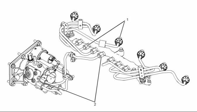
g02293673
Illustration 2
Typical example
(1), (2) Tighten the nuts on the high-pressure fuel
lines to the following torque. ..... 40 N·m (30 lb ft)
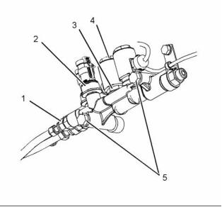
i04085749
Fuel Injection Pump
Note: The timing of the fuel injection pump will need
to be checked by trained personnel. In order to check
the timing of the fuel injection pump, refer to Systems
Operation, Testing and Adjusting, “Fuel Injection
Pump Timing - Check”.
NOTICE
Refer to Systems Operation, Testing and Adjust-
ing, “Cleanliness of Fuel System Components” for
detailed information on the standards of cleanli-
ness that must be observed during ALL work on
the fuel system.
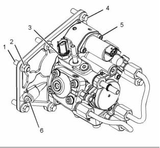
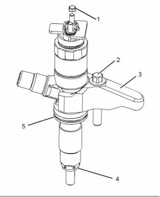
g02293713
Illustration 3
Typical example
(1) Tighten the studs to the following torque. .. 11 N·m
(97 lb in)
(2) Tighten the mounting nut to the following
torque. ...................................... 22 N·m (16 lb ft)
(3) Tighten the fuel temperature sensor to the
following torque. ....................... 22 N·m (16 lb ft)
This document is printed from SPI². Not for RESALE
![]()
![]()
![]()
![]()
![]()
6
KENR8798-01
Specifications Section
(4) Tighten the setscrews to the following
i04083730
torque. ...................................... 22 N·m (16 lb ft)
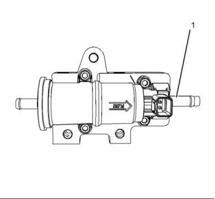
Fuel Transfer Pump
(5) Tighten the screws for the suction control valve
to the following torque. ............... 9 N·m (80 lb in)
(6) Tighten the screw to the following
torque. ...................................... 14 N·m (10 lb ft)
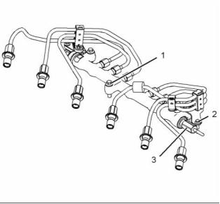
i03631793
Fuel Injectors
NOTICE
Refer to Systems Operation, Testing and Adjust-
ing, “Cleanliness of Fuel System Components” for
detailed information on the standards of cleanli-
ness that must be observed during ALL work on
the fuel system.
g02291814
Illustration 5
Typical example
(1) Tighten the connection to the following
torque. ...................................... 20 N·m (15 lb ft)
g01862457
Illustration 4
Typical example
(3) Clamp
(4) Washer
(5) O ring seal
g02291815
Illustration 6
Typical example
(2), (3) Tighten the bolts to the following
torque. ...................................... 22 N·m (16 lb ft)
(1) Torque for the nuts ...................... 2 N·m (18 lb in)
(2) Torque for the bolt in the clamp for the fuel
injection nozzle ...................... 21 N·m (15.5 lb ft)
This document is printed from SPI². Not for RESALE
![]()
![]()
![]()
![]()
![]()
![]()
KENR8798-01
7
Specifications Section
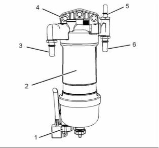
i04073889
i04081471
Fuel Filter Base
(Single Secondary Fuel Filter
Base)
Fuel Filter Base
(Twin Secondary Fuel Filter
Base)
NOTICE
NOTICE
Refer to Systems Operation, Testing and Adjust-
ing, “Cleanliness of Fuel System Components” for
detailed information on the standards of cleanli-
ness that must be observed during ALL work on
the fuel system.
Refer to Systems Operation, Testing and Adjust-
ing, “Cleanliness of Fuel System Components” for
detailed information on the standards of cleanli-
ness that must be observed during ALL work on
the fuel system.
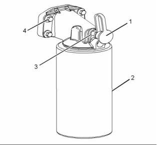
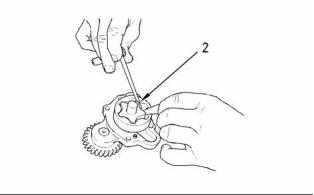
If necessary, install a new fuel filter (2) to canister (1).
Refer to Operation and Maintenance Manual, “Fuel
System Secondary Filter - Replace” for the correct
procedure.
If necessary, install a new fuel filter (2) to canister (1).
Refer to Operation and Maintenance Manual, “Fuel
System Secondary Filter - Replace” for the correct
procedure.
g02289913
Illustration 7
Typical example
(3) Tighten the bolts to the following torque. .. 44 N·m
(33 lb ft)
(4) Tighten the bolt to the following torque. ... 17 N·m
(13 lb ft)
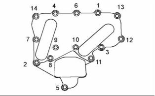
g02289934
Illustration 8
Typical example
(5) Tighten the differential pressure switch (if
equipped) to the following torque. ........... 20 N·m
(15 lb ft)
(3) Tighten the bolts to the following torque. .. 44 N·m
(33 lb ft)
(4) Tighten the differential pressure switch (if
equipped) to the following torque. ........... 17 N·m
(13 lb ft)
(5) Tighten the bolt to the following torque. ... 20 N·m
(15 lb ft)
This document is printed from SPI². Not for RESALE
![]()
![]()
![]()
![]()
![]()
![]()
![]()
8
KENR8798-01
Specifications Section
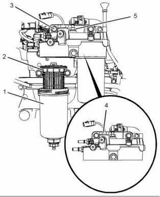
i04077229
i04224205
Fuel Filter Base
(Primary Fuel Filter Base)
Fuel Control Manifold
(Aftertreatment Regeneration
Device)
NOTICE
Refer to Systems Operation, Testing and Adjust-
ing, “Cleanliness of Fuel System Components” for
detailed information on the standards of cleanli-
ness that must be observed during ALL work on
the fuel system.
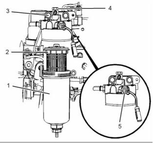
If necessary, install a new fuel filter element to
canister (2). Refer to Operation and Maintenance
Manual, “Fuel System Primary Filter (Water
Separator) Element - Replace” for the correct
procedure.
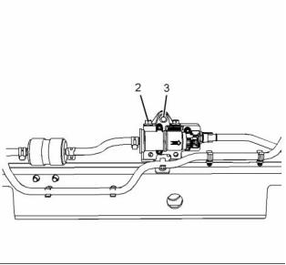
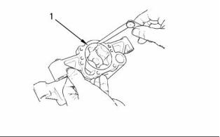
g01942619
Illustration 10
Typical example
(1) Tighten the connectors for the fuel control
manifold to the following torque. .............. 43 N·m
(32 lb ft)
(2) Tighten the fuel pressure sensor for the fuel
control manifold to the following torque. .. 20 N·m
(15 lb ft)
(3) Tighten the fuel pilot valve assembly to the
following torque. ....................... 50 N·m (37 lb ft)
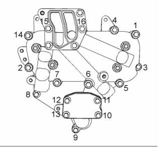
g02289936
Illustration 9
Typical example
(4) Tighten the nut for the coil to the following
torque. ...................................... 20 N·m (15 lb ft)
Tighten water in fuel sensor (1) hand tight.
(5) Tighten the setscrews for the fuel manifold to the
following torque. ....................... 55 N·m (41 lb ft)
(3) Tighten the connection to the following
torque. ...................................... 20 N·m (15 lb ft)
(4) Tighten the bolts to the following torque. .. 44 N·m
(32 lb ft)
i04084390
Fuel Manifold (Rail)
(5) Tighten the connection to the following
torque. ...................................... 20 N·m (15 lb ft)
(6) Tighten the connection to the following
torque. ...................................... 20 N·m (15 lb ft)
Refer to Operation and Maintenance Manual,
“General Hazard Information and High Pressure Fuel
Lines” before adjustments and repairs are performed.
This document is printed from SPI². Not for RESALE
![]()
![]()
![]()
![]()
![]()
KENR8798-01
9
Specifications Section
i03537811
NOTICE
Lifter Group
Refer to Systems Operation, Testing and Adjust-
ing, “Cleanliness of Fuel System Components” for
detailed information on the standards of cleanli-
ness that must be observed during ALL work on
the fuel system.
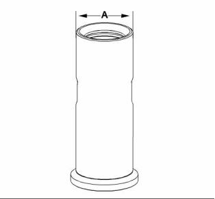
g01866794
Illustration 12
g02293653
Illustration 11
Typical example
Typical example
(A) Diameter of the lifter body .. 21.938 to 21.963 mm
(0.86370 to 0.86468 inch)
(1) Tighten the bolts to the following torque. .. 22 N·m
(16 lb ft)
Bore diameter in the cylinder block
...... 22.000 to 22.032 mm (0.86614 to 0.86740 inch)
(2) Tighten the bolts to the following torque. .. 10 N·m
(89 lb in)
Clearance
(3) Tighten the fuel pressure relief valve to the
following torque. ....................... 30 N·m (22 lb ft)
Clearance of the lifter .......... 0.037 to 0.094 mm
(0.00146 to 0.00370 inch)
Note: The fuel pressure relief valve (3) should be
tightened an additional 24 degrees.
This document is printed from SPI². Not for RESALE
![]()
![]()
![]()
![]()
![]()
10
KENR8798-01
Specifications Section
i03519944
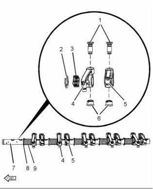
(7) Rocker shaft
Rocker Shaft
Diameter of the rocker
shaft .................................. 24.962 to 24.987 mm
(0.98275 to 0.98374 inch)
(8) Retaining clip
(9) Spring
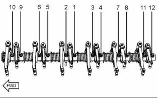
g01850497
Illustration 14
Tightening sequence
Tighten the fasteners in the sequence that is in
illustration 14. Tighten the fasteners to the following
torque. ............................................. 35 N·m (26 lb ft)
g02113434
Illustration 13
Typical example
(1) Tighten the threaded inserts to the following
torque. ...................................... 30 N·m (22 lb ft)
(2) Retaining clip
(3) Spring
(4) Inlet rocker arm
Diameter of the rocker arm bore
.... 25.013 to 25.051 mm (0.9848 to 0.9863 inch)
(5) Exhaust rocker arm
Diameter of the rocker arm bore
.... 25.013 to 25.051 mm (0.9848 to 0.9863 inch)
Clearance
Maximum clearance of both the rocker arm
bores. ............................ 0.089 mm (0.0035 inch)
The service limit for both rocker arm
bores ............................... 0.17 mm (0.0067 inch)
(6) Guide
This document is printed from SPI². Not for RESALE
![]()
![]()
![]()
KENR8798-01
11
Specifications Section
i03532881
Valve Mechanism Cover
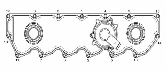
g01861234
i03538600
Illustration 15
Typical example
Tighten the bolts for the valve mechanism cover in
the sequence that is shown in illustration 15. Torque
for the bolts ....................................... 9 N·m (80 lb in)
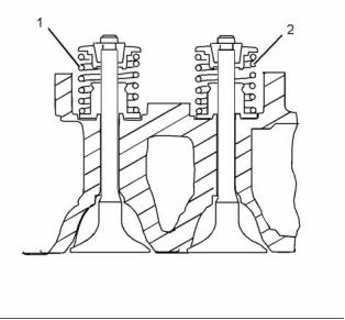
Cylinder Head Valves
g01927355
Illustration 16
Typical example
(1) Exhaust valve spring
(2) Inlet valve spring
This document is printed from SPI². Not for RESALE
![]()
![]()
![]()
12
KENR8798-01
Specifications Section
When the valve springs are replaced the valve
springs must be replaced in pairs.
The service limit for the inlet valve
stem ................................ 0.08 mm (0.0031 inch)
Refer to table 1 and table 2 for information on the
length of the valve spring and the load of the valve
spring.
Clearance
Maximum clearance of the exhaust valve
stem ............................ 0.075 mm (0.00295 inch)
The service limit for the exhaust valve
Table 1
stem .............................. 0.10 mm (0.00394 inch)
The load for the inlet valve The length of the inlet valve
spring
spring
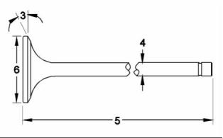
(5) Length of valve
161.5 to 178.5 N
(36.30682 to 40.12859 lb)
31.5 mm (1.2402 inch)
Inlet valve .......................... 109.82 to 110.27 mm
(4.32361 to 4.34133 inch)
Exhaust valve ................ 109.853 to 110.303 mm
(4.32491 to 4.34263 inch)
337.9 to 373.5 N
(75.96330 to 83.96654 lb)
21.5 mm (0.84646 inch)
Note: The free length for the inlet valve spring is
40.65 mm (1.60039 inch).
(6) Valve head
Diameter of inlet valve head .................... 35 mm
(1.37795 inch)
Table 2
Diameter of exhaust valve head .............. 33 mm
(1.2992 inch)
The load for the exhaust
valve spring
The length of the exhaust
valve spring
285 to 315 N
31.5 mm (1.2402 inch)
(64.07085 to 70.81515 lb)
i04131371
Cylinder Head
408.5 to 451.5 N
(91.83488 to 101.50172 lb)
22.3 mm (0.87795 inch)
Note: The free length for the exhaust valve spring is
52.73 mm (2.07598 inch).
g01927357
Illustration 17
Typical example
(3) Valve face angle
Inlet ................................................... 30 degrees
Exhaust ............................................. 45 degrees
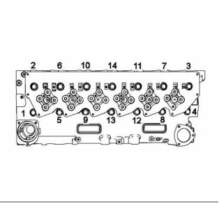
g01852017
Illustration 18
Typical example
(4) Valve stem diameter
Lubricate the threads and the underside of the head
bolts with clean engine oil.
Inlet .. 6.970 to 6.985 mm (0.2744 to 0.2750 inch)
Exhaust ................................. 6.945 to 6.960 mm
(0.2734 to 0.2740 inch)
Tighten the bolts in the sequence that is shown in
illustration 18. Torque for the bolts ........... 50 N·m
(37 lb ft)
Clearance
Tighten the bolts again to the following
torque. .................................... 100 N·m (74 lb ft)
Maximum clearance of the inlet valve
stem ................................ 0.05 mm (0.0020 inch)
This document is printed from SPI². Not for RESALE
![]()


![]()
![]()
KENR8798-01
13
Specifications Section
Tighten the head bolts to the additional
amount. ........................................... 225 degrees
Minimum thickness of cylinder head ......... 150.8 mm
(5.93700 inch)
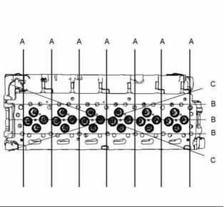
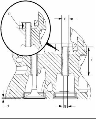
g01854993
Illustration 19
g02328933
Typical example
Illustration 20
Typical example
Note: The maximum distortion of the cylinder head
is given in table 3.
(D) Valve guide height from the top of the valve guide
to the valve spring seat .......... 10.75 to 11.25 mm
(0.42323 to 0.44291 inch)
Table 3
Maximum Permissible
Dimension
Distortion
(E) Outside diameter of the valve
guides ................................ 11.029 to 11.040 mm
(0.43421 to 0.43464 inch)
Width (A)
Length (B)
0.03 mm (0.0012 inch)
0.05 mm (0.0020 inch)
0.05 mm (0.020 inch)
(F) Length of the valve guides ... 43.75 to 44.25 mm
(1.72244 to 1.74212 inch)
Diagonal Line (C)
(G) Internal diameter of the valve
guides ................................... 7.007 to 7.020 mm
(0.27587 to 0.27638 inch)
(H) Valve depths
Inlet .. 0.905 to 1.163 mm (0.0356 to 0.0458 inch)
The service limit for the depth of the inlet valve
........................................ 1.41 mm (0.0555 inch)
Exhaust ................................. 0.876 to 1.131 mm
(0.0345 to 0.0445 inch)
The service limit for the exhaust valve
depth ............................... 1.38 mm (0.0543 inch)
This document is printed from SPI². Not for RESALE
![]()
![]()

![]()
14
KENR8798-01
Specifications Section
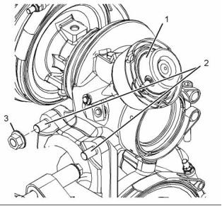
g02299037
Illustration 22
Typical example
(1) Actuator
The test pressure for the wastegate
actuator ........................................ 100 kPa (14.5 psi)
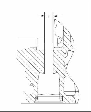
g02329114
Illustration 21
Typical example
The movement for the rod actuator ................. 1 mm
(0.0394 inch)
(J) Diameter of the parent bore in the cylinder
head ................................... 11.000 to 11.022 mm
(0.43307 to 0.43394 inch)
(2) Tighten the studs to the following
torque. ...................................... 18 N·m (13 lb ft)
(3) Tighten the nuts to the following torque. .. 44 N·m
(32 lb ft)
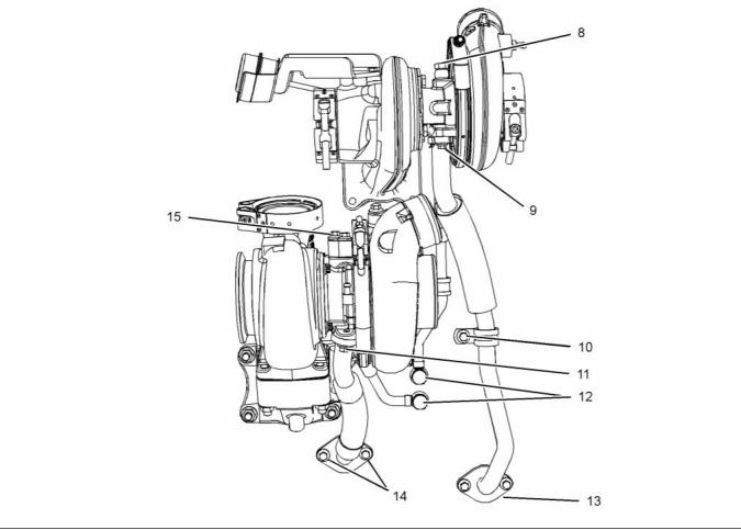
i04089709
Turbocharger
(Series Turbochargers)
Note: For the correct procedure to install the
turbochargers, refer to Disassembly and Assembly,
“Turbocharger - Install”.
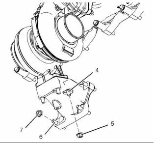
g02299038
Illustration 23
Typical example
This document is printed from SPI². Not for RESALE
![]()
![]()
![]()
![]()
KENR8798-01
15
Specifications Section
(4), (6) Tighten the studs to the following
torque. ...................................... 18 N·m (13 lb ft)
(5), (7) Tighten the nuts to the following
torque. ...................................... 44 N·m (32 lb ft)
g02297816
Illustration 24
Typical example
(8) Tighten the bolt to the following torque. ... 15 N·m
(11 lb ft)
(9) Tighten the bolts to the following torque. ... 9 N·m
(80 lb in)
(10) Tighten the bolt to the following torque. .. 18 N·m
(13 lb ft)
(11), (13), (14), (15) Tighten the bolts to the following
torque. ...................................... 22 N·m (16 lb ft)
(12) Tighten the bolt to the following torque. .. 33 N·m
(24 lb ft)
This document is printed from SPI². Not for RESALE
![]()
![]()
16
KENR8798-01
Specifications Section
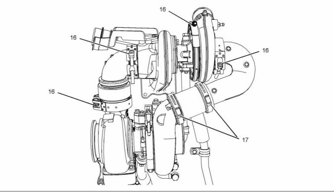
g02297313
i04087589
Illustration 25
Typical example
(16) Tighten the band clamps for the turbochargers
to the following torque. ........... 12 N·m (106 lb in)
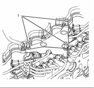
Exhaust Gas Valve (NRS)
(17) Tighten the band clamps for the ducts to the
following torque. ......................... 6 N·m (53 lb in)
g01946893
Illustration 26
Typical example
This document is printed from SPI². Not for RESALE
![]()
![]()
![]()
KENR8798-01
17
Specifications Section
(1) Tighten the bolts to the following torque. .. 22 N·m
(16 lb ft)
g02295533
Illustration 27
Typical example
(2) Tighten the bolts to the following torque. .. 18 N·m
(13 lb ft)
(3) Tighten the bolts to the following torque. .. 22 N·m
(16 lb ft)
(4) Tighten the clamps to the following
torque. ........................................ 7 N·m (62 lb in)
(5) Tighten the bolt to the following torque. ... 18 N·m
(13 lb ft)
g02295655
Illustration 28
Typical example
(6) Tighten the bolt to the following torque. ... 15 N·m
(11 lb ft)
(7), (8) Tighten the fasteners to the following
torque. ...................................... 18 N·m (13 lb ft)
This document is printed from SPI². Not for RESALE
![]()
![]()
![]()
18
KENR8798-01
Specifications Section
i03636414
Exhaust Sensor and Lines Gp
(NRS)
Table 4
Required Tools
Tool
Part Number
Part Description
Qty
Bostik Pure Nickel
Anti-Seize Compound
A
-
1
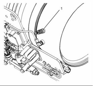
g01950927
Illustration 29
Typical example
Note: Apply Tooling (A) to the sensors before the
sensors are installed.
(1) Tighten the sensors to the following
torque. ...................................... 45 N·m (33 lb ft)
Tighten the harness for the sensors (not shown) to
the following torque. ........................ 45 N·m (33 lb ft)
i04087771
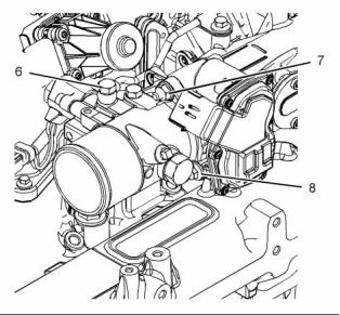
Exhaust Cooler (NRS)
Note: When the pipes for the exhaust cooler are
removed or installed, care must be taken so that the
pipes are not bent or damaged.
This document is printed from SPI². Not for RESALE
![]()

![]()
KENR8798-01
19
Specifications Section
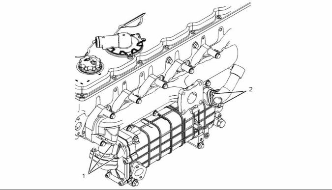
g02295833
Illustration 30
Typical example
(1) Tighten the setscrews to the following
torque. ...................................... 22 N·m (16 lb ft)
(2) Tighten the setscrews to the following
torque. ...................................... 18 N·m (13 lb ft)
This document is printed from SPI². Not for RESALE
![]()
![]()
20
KENR8798-01
Specifications Section
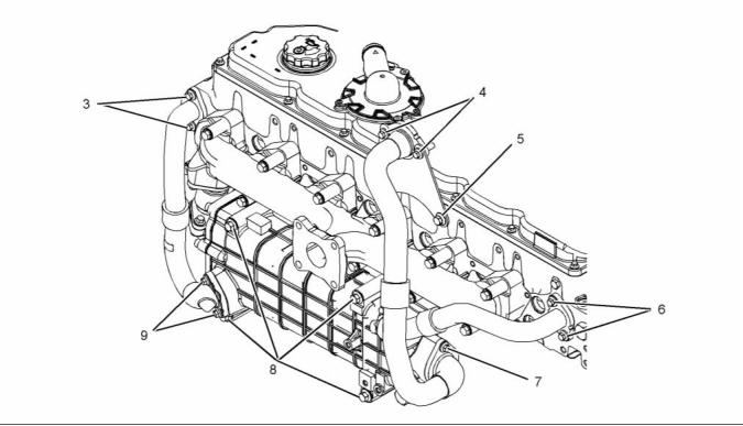
g02295755
Illustration 31
Typical example
(3), (6) Tighten the setscrews to the following
torque. ...................................... 22 N·m (16 lb ft)
(4), (7), (9) Tighten the setscrews to the following
torque. ...................................... 18 N·m (13 lb ft)
(5), (8) Tighten the setscrews to the following
torque. ...................................... 44 N·m (32 lb ft)
This document is printed from SPI². Not for RESALE
![]()
![]()
KENR8798-01
21
Specifications Section
i04133329
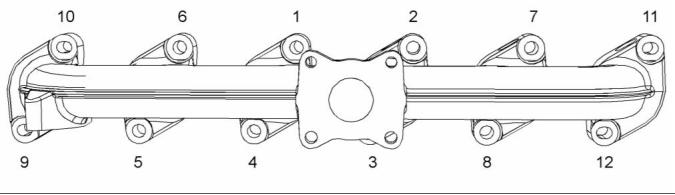
Exhaust Manifold
g02330776
Illustration 32
Typical example
Tighten the exhaust manifold bolts in the sequence
that is shown in illustration 32 to the following
torque. ............................................. 44 N·m (32 lb ft)
This document is printed from SPI². Not for RESALE
![]()
![]()
22
KENR8798-01
Specifications Section
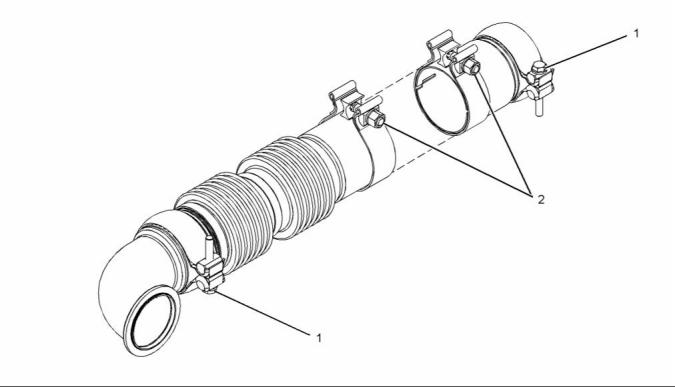
i03936932
Flexible Exhaust Pipe
g02155429
Illustration 33
Typical example
(1) Tighten the clamp to the following
torque. ...................................... 35 N·m (26 lb ft)
(2) Tighten the clamp to the following
torque. ...................................... 55 N·m (41 lb ft)
Refer to Disassembly and Assembly for the correct
procedure to install the flexible exhaust pipe.
i04083749
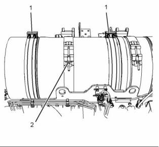
Diesel Particulate Filter
Note: To remove and install the Diesel Particulate
Filter (DPF), refer to Disassembly and Assembly
for the correct procedures.
g02291874
Illustration 34
Typical example
This document is printed from SPI². Not for RESALE
![]()
![]()
![]()
KENR8798-01
23
Specifications Section
(1) Tighten the nuts on the clamps to the following
torque. ...................................... 42 N·m (31 lb ft)
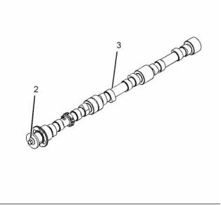
i04156668
Camshaft
(2) Tighten the nuts on the clamp to the following
torque. ...................................... 18 N·m (13 lb ft)
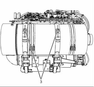
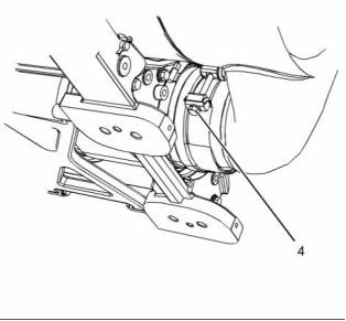
g02291875
Illustration 35
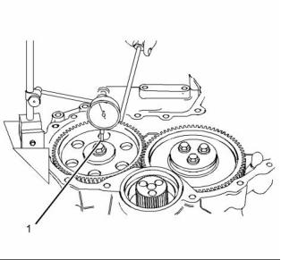
g01927854
Typical example
Illustration 37
Checking the end play of the camshaft
(3) Tighten the nuts on the clamps to the following
torque. ...................................... 18 N·m (13 lb ft)
(1) End play of a camshaft ......... 0.106 to 0.558 mm
(0.00417 to 0.02197 inch)
Maximum permissible end play of a worn
camshaft ............................... 0.62 mm (0.0244 inch)
g02291876
Illustration 36
Typical example
(4) Tighten the nuts to the following torque. .. 18 N·m
(13 lb ft)
g01859007
Illustration 38
Typical example
(2) Bolt
Torque for the 8.8 graded bolt .. 95 N·m (70 lb ft)
This document is printed from SPI². Not for RESALE
![]()
![]()
![]()
![]()
![]()
24
KENR8798-01
Specifications Section
Torque for the 10.9 graded bolt ............. 120 N·m
(89 lb ft)
i03551117
Engine Oil Filter Base
(3) The diameters of the camshaft journals are given
in the following tables.
Table 5
Camshaft Journals
from the Front End
of the Engine
Standard Diameter
1
Front
50.711 to 50.737 mm
(1.9965 to 1.9975 inch)
50.457 to 50.483 mm
(1.9865 to 1.9875 inch)
2
3
50.203 to 50.229 mm
(1.9765 to 1.9775 inch)
4
Rear
49.949 to 49.975 mm
(1.9665 to 1.9675 inch)
Maximum wear on the camshaft journals ... 0.05 mm
(0.0021 inch)
Check the camshaft lobes for visible damage. If a
new camshaft is installed, you must install new lifters.
g01877935
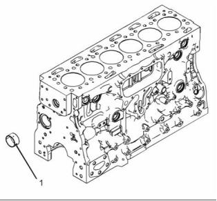
i03530782
Illustration 40
Camshaft Bearings
Typical example
(1) Dust cap
(2) Engine oil filter
Torque for the engine oil filter .. 12 N·m (106 lb in)
(3) Engine oil sampling valve
Torque for the engine oil sampling valve (if
equipped) ................................ 12 N·m (106 lb in)
Torque for the plug (if equipped) ... 12 N·m (106 lb in)
(4) Setscrew
Torque for the setscrews that retain the oil filter
base .......................................... 22 N·m (16 lb ft)
g01859293
Illustration 39
Typical example
(1) The diameter of the installed camshaft
bearing .............................. 50.787 to 50.848 mm
(1.9995 to 2.0019 inch)
This document is printed from SPI². Not for RESALE
![]()

![]()
![]()
KENR8798-01
25
Specifications Section
i03524541
Tighten the setscrews in the sequence that is in
illustration 42 to the following torque. ...... 22 N·m
(16 lb ft)
Engine Oil Cooler
i04085774
Engine Oil Pump
Engine Oil Cooler with a Low
Mounted Filter Base
Type ............................. Gear-driven differential rotor
Number of lobes
Inner rotor ......................................................... 6
Outer rotor ........................................................ 7
g02005253
Illustration 41
Typical example
Setscrews
Tighten the setscrews in the sequence that is in
illustration 41 to the following torque. ...... 22 N·m
(16 lb ft)
g00938064
Illustration 43
Engine Oil Cooler with a High
Mounted Filter Base
(1) Clearance of the outer rotor to the
body ...................................... 0.050 to 0.330 mm
(0.0020 to 0.0130 inch)
g00938061
Illustration 44
Checking the clearance
(2) Service limit of inner rotor to outer
rotor ...................................... 0.080 to 0.250 mm
(0.0031 to 0.0098 inch)
g01854213
Illustration 42
Typical example
Setscrews
This document is printed from SPI². Not for RESALE
![]()
![]()
![]()
![]()
![]()
26
KENR8798-01
Specifications Section
i03540441
Engine Oil Pressure
The minimum oil pressure at a maximum engine
speed of 2200 rpm and at normal operating
temperature is the following value. .. 315 kPa (45 psi)
g00938799
Illustration 45
Checking the end play
(3) End play of rotor assembly
Inner rotor ............................. 0.050 to 0.180 mm
(0.0020 to 0.0071 inch)
Outer rotor ............................ 0.050 to 0.180 mm
(0.0020 to 0.0071 inch)
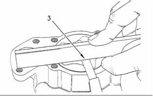
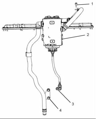
g02293754
Illustration 46
Typical example
(4) Suction Pipe
(6) Bracket for the Suction Pipe
(5), (7), (8), (9) Tighten the bolts to the following
torque. ...................................... 22 N·m (16 lb ft)
(10) Tighten the bolt to the following torque. .. 44 N·m
(32 lb ft)
This document is printed from SPI². Not for RESALE
![]()
![]()
![]()
KENR8798-01
27
Specifications Section
i04129089
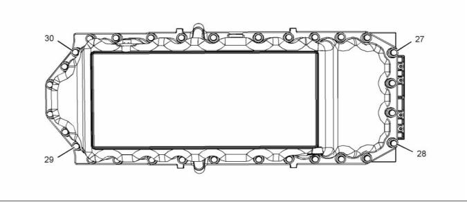
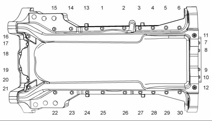
Engine Oil Pan
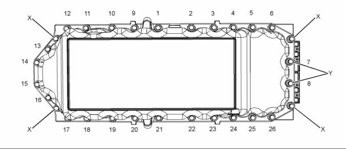
g01856874
Illustration 47
(X) Guide studs
(Y) Short fastener
Tighten the fasteners in the sequence that is shown
in illustration 47. Torque for the fasteners ...... 22 N·m
(16 lb ft)
g01857014
Illustration 48
Remove the guide studs. Install the fasteners (27),
(28), (29) and (30).
Tighten the oil drain plug to the following
torque. ............................................. 34 N·m (25 lb ft)
Tighten the fastener in the sequence that is shown in
illustration 48. Torque for the fasteners .......... 22 N·m
(16 lb ft)
Tighten the oil level switch (if equipped) to the
following torque. .............................. 34 N·m (25 lb ft)
This document is printed from SPI². Not for RESALE
![]()
![]()
![]()
28
KENR8798-01
Specifications Section
Refer to the Disassembly and Assembly, “Engine Oil
Pan” for the correct procedure to install the engine
oil pan.
The Cast Iron Oil Pan
g01397669
Illustration 49
Tightening sequence
Tighten the fasteners in the sequence that is shown
in illustration 49 to the following torque. ......... 22 N·m
(16 lb ft)
Tighten the oil drain plug to the following
torque. ............................................. 34 N·m (25 lb ft)
Tighten the oil level switch (if equipped) to the
following torque. .............................. 34 N·m (25 lb ft)
This document is printed from SPI². Not for RESALE
![]()
![]()
KENR8798-01
29
Specifications Section
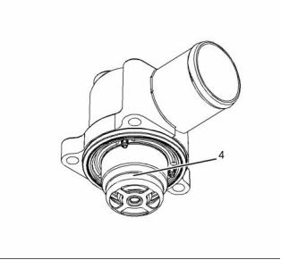
i04085789
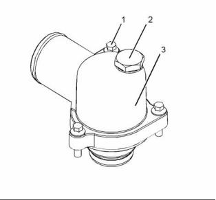
i03520180
Water Temperature Regulator
and Housing
Crankcase Breather
g01853873
Illustration 51
Typical example
Water temperature regulator housing
(1) Torque for the bolts that fasten the housing to the
cylinder head ............................ 22 N·m (16 lb ft)
g02295333
Illustration 50
Typical example
(2) Torque for the vent plug ....... 22 N·m (16.22 lb ft)
(1), (2), (3) Tighten the setscrews to the following
torque. ...................................... 22 N·m (16 lb ft)
(4) Tighten the setscrews to the following
torque. ...................................... 44 N·m (32 lb ft)
Note: If a hexagonal pillar spacer is required, install
the spacer to the engine oil cooler. Tighten the spacer
to a torque of 22 N·m (16 lb ft).
g01854133
Illustration 52
(4) Water temperature regulator
This document is printed from SPI². Not for RESALE
![]()
![]()
![]()
![]()
30
KENR8798-01
Specifications Section
Opening temperature ........................ 80° to 84°C
(151° to 176°F)
Maximum open length of 11 mm (0.43307 inch) is
achieved at the following temperature. ...... 94° C
(201° F)
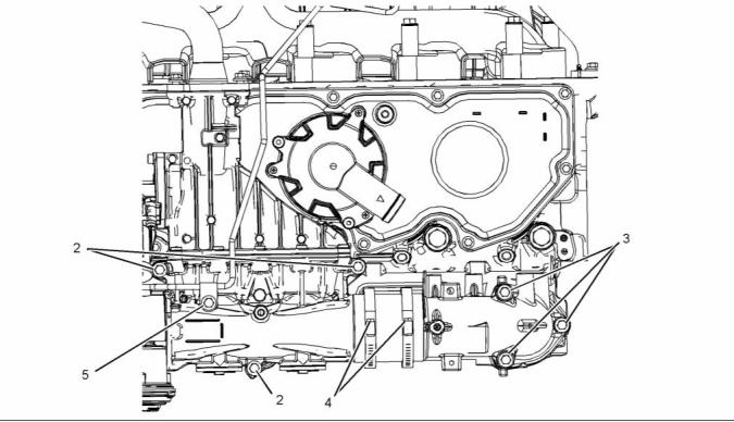
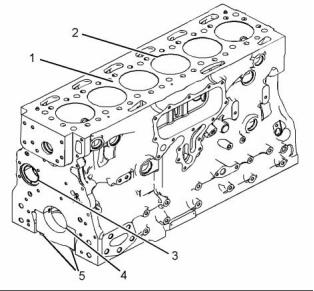
i04117792
Cylinder Block
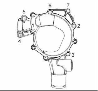
i03520301
Water Pump
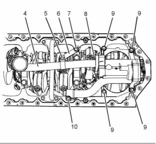
g01855114
Illustration 54
Cylinder block
(1) Cylinder block
(2) Cylinder bore ................ 105.000 to 105.025 mm
(4.1338 to 4.1348 inch)
g01850741
Illustration 53
Tightening sequence
(3) Camshaft bearings
Tighten the setscrews in the numerical sequence
that is shown in illustration 53 to the following
torque. ............................................. 22 N·m (16 lb ft)
Diameter of the bushing in the cylinder
block for the number 1 camshaft
bearing .............................. 55.563 to 55.593 mm
(2.1875 to 2.1887 inch)
Diameter of the bore in the cylinder
block for the number 2 camshaft
journal ............................... 50.546 to 50.597 mm
(1.9900 to 1.9920 inch)
Diameter of the bore in the cylinder
block for the number 3 camshaft
journal ............................... 50.292 to 50.343 mm
(1.9800 to 1.9820 inch)
Diameter of the bore in the cylinder
block for the number 4 camshaft
journal ............................... 50.038 to 50.089 mm
(1.9700 to 1.9720 inch)
(4) Main bearings
Bore in the cylinder block for the main
bearings ............................ 88.246 to 88.272 mm
(3.4742 to 3.4753 inch)
(5) Main bearing cap bolts
This document is printed from SPI². Not for RESALE
![]()
![]()
![]()
免费热线
400-100-8969 15088860848
400-100-8969 15088860848
机组销售
0574-26871589 15267810868
0574-26871589 15267810868
配件销售
0574-26886646 15706865167
0574-26886646 15706865167
维修热线
0574-26871569 18658287286
0574-26871569 18658287286
手机端

微信公众号