 English
 Espaol
 Franais
 阿拉伯
阿拉伯 中文(简)
中文(简) Deutsch
 Italiano
 Português
 日本
日本 韩国
韩国 български
 hrvatski
 esky
esky Dansk
Dansk Nederlands
 suomi
suomi Ελληνικ
 印度
印度 norsk
norsk Polski
 Roman
Roman русский
 Svenska
 珀金斯Perkins2306A(C)-E14用户手册,珀金斯Perkins2306A(C)-E14用户手册技术支持中心,珀金斯Perkins2306A(C)-E14用户手册代理商,珀金斯Perkins2306A(C)-E14用户手册销售服务中心,珀金斯Perkins2306A(C)-E14用户手册价格规格资料查询,宁波日昕动力科技有限公司

珀金斯Perkins2306A(C)-E14用户手册
详细描述
Perkins 2300 Series
Models 2306A-E14 and 2306C-E14
USER’S HANDBOOK
6 cylinder turbocharged diesel engines for industrial
applications
This publication is divided into six chapters:
1 General information
2 Engine views
3 Operation instructions
4 Preventive maintenance
5 Engine fluids
6 Fault diagnosis
The pages which follow contain a detailed table of contents
ii
This document is printed from SPI². Not for RESALE
![]()
![]()
2300 Series
Contents
1 General information
Introduction . ... ... ... ... ... ... ... ... ... ... ... ... ... ... ... ... ... ... ... ... ... ... ... ... ... ... ... ... ... .. 1
Safety precautions .. ... ... ... ... ... ... ... ... ... ... ... ... ... ... ... ... ... ... ... ... ... ... ... ... ... ... .. 2
How to care for your engine ... ... ... ... ... ... ... ... ... ... ... ... ... ... ... ... ... ... ... ... ... ... ... .. 4
Engine lift equipment .. ... ... ... ... ... ... ... ... ... ... ... ... ... ... ... ... ... ... ... ... ... ... ... ... ... .. 4
Welding ... ... ... ... ... ... ... ... ... ... ... ... ... ... ... ... ... ... ... ... ... ... ... ... ... ... ... ... ... ... ... .. 4
Engine preservation ... ... ... ... ... ... ... ... ... ... ... ... ... ... ... ... ... ... ... ... ... ... ... ... ... ... .. 4
Parts and service ... ... ... ... ... ... ... ... ... ... ... ... ... ... ... ... ... ... ... ... ... ... ... ... ... ... ... .. 4
Service literature . ... ... ... ... ... ... ... ... ... ... ... ... ... ... ... ... ... ... ... ... ... ... ... ... ... ... ... .. 4
Training ... ... ... ... ... ... ... ... ... ... ... ... ... ... ... ... ... ... ... ... ... ... ... ... ... ... ... ... ... ... ... .. 4
Engine identification ... ... ... ... ... ... ... ... ... ... ... ... ... ... ... ... ... ... ... ... ... ... ... ... ... ... .. 5
Engine data . ... ... ... ... ... ... ... ... ... ... ... ... ... ... ... ... ... ... ... ... ... ... ... ... ... ... ... ... ... .. 6
2 Engine views
Introduction . ... ... ... ... ... ... ... ... ... ... ... ... ... ... ... ... ... ... ... ... ... ... ... ... ... ... ... ... ... .. 7
Location of engine parts .. ... ... ... ... ... ... ... ... ... ... ... ... ... ... ... ... ... ... ... ... ... ... ... ... .. 7
3 Operation instructions
How to start the engine ... ... ... ... ... ... ... ... ... ... ... ... ... ... ... ... ... ... ... ... ... ... ... ... ... .. 9
How to start a new, an overhauled engine or an engine which has been in storage .. ... .. 9
How to start a cold engine in cold conditions .. ... ... ... ... ... ... ... ... ... ... ... ... ... ... ... ... 11
After the engine has started ... ... ... ... ... ... ... ... ... ... ... ... ... ... ... ... ... ... ... ... ... ... ... 12
Engine emergency stop .. ... ... ... ... ... ... ... ... ... ... ... ... ... ... ... ... ... ... ... ... ... ... ... ... 12
Manual stop procedure ... ... ... ... ... ... ... ... ... ... ... ... ... ... ... ... ... ... ... ... ... ... ... ... ... 12
User’s Handbook, TSD3454E, Issue 2
iii
This document is printed from SPI². Not for RESALE
![]()
![]()
2300 Series
Engine diagnostics .. ... ... ... ... ... ... ... ... ... ... ... ... ... ... ... ... ... ... ... ... ... ... ... ... ... ... 13
4 Preventive maintenance
Preventive maintenance periods . ... ... ... ... ... ... ... ... ... ... ... ... ... ... ... ... ... ... ... ... ... 15
Schedule .. ... ... ... ... ... ... ... ... ... ... ... ... ... ... ... ... ... ... ... ... ... ... ... ... ... ... ... ... ... ... 16
How to check the amount of the coolant . ... ... ... ... ... ... ... ... ... ... ... ... ... ... ... ... ... ... 17
How to check the air cleaner service indicator ... ... ... ... ... ... ... ... ... ... ... ... ... ... ... ... 17
How to check the amount of lubricating oil .. ... ... ... ... ... ... ... ... ... ... ... ... ... ... ... ... ... 18
How to drain the primary fuel filter ... ... ... ... ... ... ... ... ... ... ... ... ... ... ... ... ... ... ... ... ... 18
Visual inspection .. ... ... ... ... ... ... ... ... ... ... ... ... ... ... ... ... ... ... ... ... ... ... ... ... ... ... ... 19
Diagnostics check ... ... ... ... ... ... ... ... ... ... ... ... ... ... ... ... ... ... ... ... ... ... ... ... ... ... ... 20
How to renew the element of the primary fuel filter . ... ... ... ... ... ... ... ... ... ... ... ... ... ... 22
How to renew the element of the secondary fuel filter . ... ... ... ... ... ... ... ... ... ... ... ... ... 24
How to check the specific gravity of the coolant .. ... ... ... ... ... ... ... ... ... ... ... ... ... ... ... 26
How to obtain an oil sample ... ... ... ... ... ... ... ... ... ... ... ... ... ... ... ... ... ... ... ... ... ... ... 27
How to renew the engine lubricating oil ... ... ... ... ... ... ... ... ... ... ... ... ... ... ... ... ... ... ... 28
How to renew the element of the lubricating oil filter ... ... ... ... ... ... ... ... ... ... ... ... ... ... 29
How to renew the air cleaner element . ... ... ... ... ... ... ... ... ... ... ... ... ... ... ... ... ... ... ... 30
How to check the drive belts ... ... ... ... ... ... ... ... ... ... ... ... ... ... ... ... ... ... ... ... ... ... ... 31
How to adjust the tension of the fan belts ... ... ... ... ... ... ... ... ... ... ... ... ... ... ... ... ... ... 31
How to adjust the tension of the alternator belt ... ... ... ... ... ... ... ... ... ... ... ... ... ... ... ... 32
How to renew the fan belts .. ... ... ... ... ... ... ... ... ... ... ... ... ... ... ... ... ... ... ... ... ... ... ... 33
How to renew the alternator belt .. ... ... ... ... ... ... ... ... ... ... ... ... ... ... ... ... ... ... ... ... ... 33
How to inspect the crankshaft vibration damper .. ... ... ... ... ... ... ... ... ... ... ... ... ... ... ... 33
Earth stud ... ... ... ... ... ... ... ... ... ... ... ... ... ... ... ... ... ... ... ... ... ... ... ... ... ... ... ... ... ... 34
Hoses and hose clips .. ... ... ... ... ... ... ... ... ... ... ... ... ... ... ... ... ... ... ... ... ... ... ... ... ... 35
How to clean the radiator . ... ... ... ... ... ... ... ... ... ... ... ... ... ... ... ... ... ... ... ... ... ... ... ... 36
How to inspect the engine mountings .. ... ... ... ... ... ... ... ... ... ... ... ... ... ... ... ... ... ... ... 36
How to drain the coolant system . ... ... ... ... ... ... ... ... ... ... ... ... ... ... ... ... ... ... ... ... ... 37
How to clean the coolant system . ... ... ... ... ... ... ... ... ... ... ... ... ... ... ... ... ... ... ... ... ... 37
How to fill the coolant system .. ... ... ... ... ... ... ... ... ... ... ... ... ... ... ... ... ... ... ... ... ... ... 37
How to check the tappet clearances ... ... ... ... ... ... ... ... ... ... ... ... ... ... ... ... ... ... ... ... 38
How to check/adjust the electronic unit injectors . ... ... ... ... ... ... ... ... ... ... ... ... ... ... ... 41
Engine protection devices ... ... ... ... ... ... ... ... ... ... ... ... ... ... ... ... ... ... ... ... ... ... ... ... 42
How to renew the thermostats of the coolant system .. ... ... ... ... ... ... ... ... ... ... ... ... ... 43
How to clean and to calibrate the engine speed/timing sensors . ... ... ... ... ... ... ... ... ... 45
iv
User’s Handbook, TSD3454E, Issue 2
This document is printed from SPI². Not for RESALE
![]()
![]()
2300 Series
How to inspect the turbocharger . ... ... ... ... ... ... ... ... ... ... ... ... ... ... ... ... ... ... ... ... ... 46
How to inspect the battery charging alternator ... ... ... ... ... ... ... ... ... ... ... ... ... ... ... ... 46
How to inspect the starter motor . ... ... ... ... ... ... ... ... ... ... ... ... ... ... ... ... ... ... ... ... ... 47
How to inspect the coolant pump ... ... ... ... ... ... ... ... ... ... ... ... ... ... ... ... ... ... ... ... ... 47
How to eliminate air from the fuel system ... ... ... ... ... ... ... ... ... ... ... ... ... ... ... ... ... ... 48
5 Engine fluids
Fuel specification ... ... ... ... ... ... ... ... ... ... ... ... ... ... ... ... ... ... ... ... ... ... ... ... ... ... ... 49
Coolant ... ... ... ... ... ... ... ... ... ... ... ... ... ... ... ... ... ... ... ... ... ... ... ... ... ... ... ... ... ... ... 49
Lubricating oil specification . ... ... ... ... ... ... ... ... ... ... ... ... ... ... ... ... ... ... ... ... ... ... ... 50
Warranty . ... ... ... ... ... ... ... ... ... ... ... ... ... ... ... ... ... ... ... ... ... ... ... ... ... ... ... ... ... ... 50
6 Fault diagnosis
Problems and possible causes ... ... ... ... ... ... ... ... ... ... ... ... ... ... ... ... ... ... ... ... ... ... 51
List of possible causes ... ... ... ... ... ... ... ... ... ... ... ... ... ... ... ... ... ... ... ... ... ... ... ... ... 52
User’s Handbook, TSD3454E, Issue 2
v
This document is printed from SPI². Not for RESALE
![]()
![]()
2300 Series
vi
User’s Handbook, TSD3454E, Issue 2
This document is printed from SPI². Not for RESALE
![]()
![]()
2300 Series
1
General information
1
Introduction
The 2306 diesel engine is the latest development from Perkins Engines Company Limited, a world leader in
the design and manufacture of high performance diesel engines. More than fifty years of diesel production
experience, together with the use of the latest technology, have been used in the manufacture of your engine
to give you reliable and economic power.
To ensure that you use the relevant information for your specific engine type, refer to "Engine identification"
on page 5.
The terms "left side" and "right side" apply when the engine is seen from the rear end, the flywheel end.
Number one cylinder is at the front end of the engine
Danger is indicated in the text by two methods:
Warning! This indicates that there is a possible danger to the person.
Caution: This indicates that there is a possible danger to the engine.
Note: Is used where the information is important, but there is not a danger.
User’s Handbook, TSD3454E, Issue 2
1
This document is printed from SPI². Not for RESALE
![]()
![]()
1
2300 Series
Safety precautions
These safety precautions are important. You must refer also to the local regulations in the country of use.
Some items only apply to specific applications.
Always refer to the text of this handbook for specific warnings and cautions.
Only use these engines in the type of application for which they have been designed.
Do not change the specification of the engine.
Do not make adjustments that you do not understand.
Do not allow the engine to stand on its sump.
Do not smoke when you put fuel in the tank.
Clean away fuel which has been spilt. Material which has been contaminated by fuel must be moved to a
safe place.
Do not put fuel in the tank while the engine runs (unless it is absolutely necessary).
Do not clean, add lubricating oil, or adjust the engine while it runs (unless you have had the correct training;
even then extreme caution must be used to prevent injury).
Ensure that the engine does not run in a location where it can cause a concentration of toxic emissions.
Other persons must be kept at a safe distance while the engine or auxiliary equipment is in operation.
Do not permit loose clothing or long hair near moving parts.
Warning! Keep away from moving parts during engine operation. Some moving parts cannot be seen clearly
while the engine runs.
Do not operate the engine if a safety guard has been removed.
Do not remove the filler cap or any component of the coolant system while the engine is hot and while the
coolant is under pressure, because dangerous hot coolant can be discharged.
Do not allow sparks or fire near the batteries (especially when the batteries are on charge) because the
gases from the electrolyte are highly flammable. The battery fluid is dangerous to the skin and especially
to the eyes.
Disconnect the battery terminals before a repair is made to the electrical system. Always disconnect the
negative terminal first.
Only one person must control the engine.
Ensure that the engine is operated only from the control panel or from the operator's position.
If your skin comes into contact with high-pressure fuel, obtain medical assistance immediately.
Diesel fuel and lubricating oil (especially used lubricating oil) can damage the skin of certain persons.
Protect your hands with gloves or a special solution to protect the skin.
Do not wear clothing which is contaminated by lubricating oil. Do not put material which is contaminated
with oil into the pockets.
Discard used lubricating oil and coolant in accordance with local regulations to prevent contamination.
The combustible material of some components of the engine (for example certain seals) can become
extremely dangerous if it is burned. Never allow this burnt material to come into contact with the skin or with
the eyes.
Continued
2
User’s Handbook, TSD3454E, Issue 2
This document is printed from SPI². Not for RESALE
![]()
![]()
![]()
![]()
![]()
![]()
![]()
![]()
![]()
![]()
![]()
![]()
![]()
![]()
![]()
![]()
![]()
![]()
![]()
![]()
![]()
![]()
![]()
![]()
![]()
1
2300 Series
Always use a safety cage to protect the operator when a component is to be pressure tested in a container
of water. Fit safety wires to secure the plugs which seal the hose connections of a component which is to
be pressure tested.
Do not allow compressed air to contact your skin. If compressed air enters your skin, obtain medical help
immediately.
Turbochargers operate at high speed and at high temperatures. Keep fingers, tools and debris away from
the inlet and outlet ports of the turbocharger and prevent contact with hot surfaces.
Some components are not waterproof and should not be washed with a high-pressure water jet or steam.
Do not wash an engine while it runs or while it is hot. If cold cleaning fluids are applied to a hot engine,
certain components on the engine could be damaged.
Fit only genuine Perkins parts.
User’s Handbook, TSD3454E, Issue 2
3
This document is printed from SPI². Not for RESALE
![]()
![]()
![]()
![]()
![]()
![]()
![]()
![]()
1
2300 Series
How to care for your engine
Warning! Read the "Safety precautions" and remember them. They are given for your protection and must be
applied at all times.
Caution: Do not clean an engine while it runs. If cold cleaning fluids are applied to a hot engine, certain
components on the engine may be damaged.
To obtain the best performance and the longest life from your engine, you must ensure that the maintenance
operations are done at the correct intervals, refer to "Preventive maintenance periods" on page 15.
Ensure that all adjustments and repairs are done by personnel who have had the correct training.
Engine lift equipment
Warning! The lifting eyes which are fitted to the engine must be used for lifting only the engine. Do NOT use
them to lift the engine if it is still attached to its driven unit.
Welding
Welding can cause damage to the electronic components fitted to the engine. If welding is necessary, the
precautions which follow must be undertaken before and during the welding operation.
Cautions:
Switch off the engine.
Disconnect the cable from the negative terminal of the battery. If the machine is fitted with a battery
disconnect the switch then open the switch.
If welding to the engine, remove the ECM (electronic control module).
If welding onto the machine chassis, ensure that the earth clamp is attached as close to the welding point
as possible and NOT near to the ECM.
If it is necessary to weld near to the ECM, remove the ECM from the engine.
Engine preservation
Details not available at time of print.
Parts and service
If problems occur with your engine or with the components fitted to it, your authorised distributor can make the
necessary repairs and will ensure that only the correct parts are fitted and that the work is done correctly.
Service literature
Workshop manuals and other service publications are available from your authorised distributor.
Training
Courses on the service and overhaul of the 2306 engine are available at the Factory. For details apply to: The
Product Training Centre, Perkins Engines Company Limited, Peterborough, PE1 5NA, England.
4
User’s Handbook, TSD3454E, Issue 2
This document is printed from SPI². Not for RESALE
![]()
![]()
![]()
![]()
![]()
![]()
![]()
1
2300 Series
Engine identification
If you need parts, service or information for your engine, you must give the complete engine number. The
engine number is stamped on a data plate which is fastened to the right side of the engine.
A typical engine number is: FGB060125U 2905J, which consists of these codes:
F
Code for engine capacity
Engine application
G
B
Engine type
06
0125
U
Number of engine cylinders
Engine specification number
The country of manufacture
Build line number
2905
J
Year of manufacture
User’s Handbook, TSD3454E, Issue 2
5
This document is printed from SPI². Not for RESALE
![]()
![]()

1
2300 Series
Engine data
Number of cylinders... ... ... ... ... ... ... ... ... ... ... ... ... ... ... ... ... ... ... ... ... ... ... ... ... ... ... ... ... ... ... ... ... ... ..6
Cylinder arrangement ... ... ... ... ... ... ... ... ... ... ... ... ... ... ... ... ... ... ... ... ... ... ... ... ... ... ... ... ... ... ... .. In line
Cycle.. ... ... ... ... ... ... ... ... ... ... ... ... ... ... ... ... ... ... ... ... ... ... ... ... ... ... ... ... ... ... ... ... ... ... ... ..Four stroke
Induction system ... ... ... ... ... ... ... ... ... ... ... ... ... ... ... ... ... ... ... ... ... ... ... ... ... ... ... ... ... ... . Turbocharged
Combustion system ... ... ... ... ... ... ... ... ... ... ... ... ... ... ... ... ... ... ... ... ... ... ... ... ... ... ... ... ... Direct injection
Nominal bore.. ... ... ... ... ... ... ... ... ... ... ... ... ... ... ... ... ... ... ... ... ... ... ... ... ... ... ... ... ... ...137 mm (5.394 in)
Nominal stroke .. ... ... ... ... ... ... ... ... ... ... ... ... ... ... ... ... ... ... ... ... ... ... ... ... ... ... ... ... ...165 mm (6.496 in)
Compression ratio.. ... ... ... ... ... ... ... ... ... ... ... ... ... ... ... ... ... ... ... ... ... ... ... ... ... ... ... ... ... ... ... ... ... .16:1
Cubic capacity ... ... ... ... ... ... ... ... ... ... ... ... ... ... ... ... ... ... ... ... ... ... ... ... ... ... ... ... ... . 14,6 litres (893 in3)
Firing order. ... ... ... ... ... ... ... ... ... ... ... ... ... ... ... ... ... ... ... ... ... ... ... ... ... ... ... ... ... ... ... ... ..1, 5, 3, 6, 2, 4
Direction of rotation ... ... ... ... ... ... ... ... ... ... ... ... ... ... ... ... ... ... ... ... ... ..Anti-clockwise viewed on flywheel
Lubricating oil capacity:
Total system... ... ... ... ... ... ... ... ... ... ... ... ... ... ... ... ... ... ... ... ... ... ... ... ... ... ... ... ... 68 litres (120 UK pints)
Sump maximum. ... ... ... ... ... ... ... ... ... ... ... ... ... ... ... ... ... ... ... ... ... ... ... ... ... ... ... 60 litres (106 UK pints)
Sump minimum.. ... ... ... ... ... ... ... ... ... ... ... ... ... ... ... ... ... ... ... ... ... ... ... ... ... ... ... . 45 litres (79 UK pints)
Lubricating oil pressure:
At rated speed ... ... ... ... ... ... ... ... ... ... ... ... ... ... ... ... ... ... ... ... ... ... ... ... ... ... ... ... ... ... ... ... ... ... .4,5 bar
Typical coolant capacity of engine. ... ... ... ... ... ... ... ... ... ... ... ... ... ... ... ... ... ... . 20,8 litres (4.6 UK gallons)
Typical coolant capacity of engine and radiator. ... ... ... ... ... ... ... ... ... ... ... ... ... .. 47 litres (10.3 UK gallons)
6
User’s Handbook, TSD3454E, Issue 2
This document is printed from SPI². Not for RESALE
![]()
![]()
2300 Series
2
Engine views
2
Introduction
Perkins engines are built for specific applications and the views which follow do not necessarily match your
engine specification.
Location of engine parts
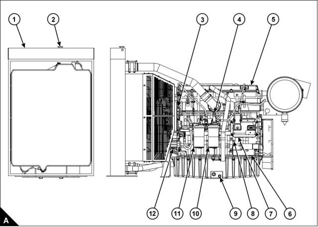
Front and left side view of engine (A)
1 Radiator
7 Electronic Control Module (ECM)
8 Earth stud
2 Radiator filler cap
3 Speed/timing sensor
4 Hand priming pump
5 Rocker cover
9 Sump drain plug
10 Secondary fuel filter
11 Primary fuel filter
6 Starter motor
12 Speed/timing sensor
User’s Handbook, TSD3454E, Issue 2
7
This document is printed from SPI². Not for RESALE
![]()
![]()
2
2300 Series
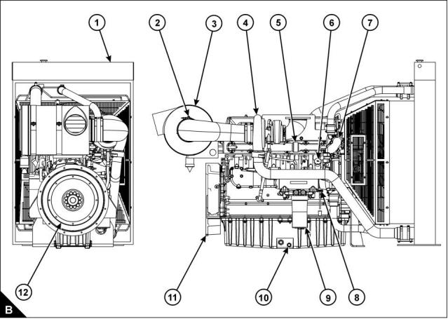
Rear and right side view of engine (B)
1 Radiator
7 Thermostat housing
8 Dipstick
2 Restriction indicator
3 Air cleaner
9 Lubricating oil filter
10 Sump drain plug
11 Flywheel housing
12 Flywheel
4 Turbocharger
5 Exhaust manifold
6 Filler cap for lubricating oil
8
User’s Handbook, TSD3454E, Issue 2
This document is printed from SPI². Not for RESALE
![]()
![]()
2300 Series
3
Operation instructions
3
How to start the engine
Before the engine is started
Perform the required daily maintenance and other periodic maintenance before the engine is started. Refer to
"Preventive maintenance periods" on page 15.
Check the fuel supply. Drain water from the water separator. Open the fuel supply valve.
Caution: All valves in the fuel return line must be open before and during engine operation to help prevent
high fuel pressure. High fuel pressure can cause failure of the filter housing or other damage.
Note: If the engine has not been started for several weeks, fuel may have drained from the fuel system. Air
may have entered the filter housing. Also, when fuel filters have been changed, some air pockets will be
trapped in the engine. If necessary refer to "How to eliminate air from the fuel system" on page 48.
Do not start the engine or move any of the controls if there is a “DO NOT OPERATE” label or similar
warning label attached to the start switch or to the controls.
Ensure that the areas around rotating parts are clear.
Reset all of the shutdown devices or alarm components.
Check the level of the engine lubricating oil. Maintain the oil level between the “L” and the “H” marks on the
dipstick.
Check the level of the coolant. Maintain the level of coolant within 13 mm (0.5 inch) of the bottom of the
filler pipe. If the engine is fitted with a sight glass, maintain the coolant level in the sight glass.
Check the service indicator for the air cleaner. When the red warning indicator is seen through the clear
panel after the engine has stopped, the air filter element must be renewed.
Ensure that any driven equipment has been disengaged. Remove any electrical loads.
How to start a new, an overhauled engine or an engine which has been in storage
Prime the turbocharger. This can be achieved by cranking the engine briefly with no fuel.
When a new engine, or an engine which has been serviced, is first started, prepare to stop the engine if an
overspeed condition occurs. Use the quickest method available, for example: Emergency Stop button.
User’s Handbook, TSD3454E, Issue 2
9
This document is printed from SPI². Not for RESALE
![]()
![]()
![]()
![]()
![]()
![]()
![]()
![]()
![]()
![]()
3
2300 Series
Start procedure
This start procedure may be used for all engines which are not fitted with an air inlet heater.
Refer to the Owner's Manual of the OEM for your type of controls. Use this procedure to start the engine:
1 Move the ignition switch to the ON position. If a system fault is indicated by, for example a panel light,
investigate the cause. If necessary use the Perkins Electronic Service Tool, EST.
2 Push the start button or turn the ignition switch to the START position to crank the engine.
3 If the engine fails to start within 30 seconds, release the start button or ignition switch. Wait for 30 seconds
to allow the starter motor to cool before attempting to start the engine again.
Note: A system fault may be indicated after the engine is started. If this occurs the ECM has detected a
problem with the system. Investigate the cause, if necessary use the Perkins service tool EST.
Caution: Oil pressure should rise within 15 seconds after the engine starts. The electronic engine controls
monitor the oil pressure and will stop the engine if the oil pressure is below normal.
4 If possible, allow the engine to run at no load for approximately three minutes. Run the engine at no load
until the water temperature gauge has started to rise. Check all gauges during the warm-up period.
10
User’s Handbook, TSD3454E, Issue 2
This document is printed from SPI². Not for RESALE
![]()
![]()
3
2300 Series
How to start a cold engine in cold conditions
Refer to the Owner's Manual of the OEM for your type of controls. Use the procedure which follows to start the
engine.
Warning! DO NOT USE ETHER. The use of ether could result in engine damage and/or personal injury.
The engine will start without aids down to a temperature of -10 °C (14 °F), but the ability to start at temperatures
below 10 °C (50 °F) will improve by the use of a cylinder block coolant heater or a device which heats the
crankcase oil. This will help to reduce white smoke and misfires when the engine is started in cold weather.
Note: If the engine has not been run for several weeks, fuel may have drained. Air may have moved into the
filter housing. Also, when fuel filters have been changed, some air will be left in the filter housing. Refer to "How
to eliminate air from the fuel system" on page 48.
1 Move the ignition switch to the ON position. If a system fault is indicated by, for example a panel light,
investigate the cause. If necessary use the Perkins Electronic Service Tool, EST.
2 Push the start button or turn the ignition switch to the START position to crank the engine.
3 If the engine fails to start within 30 seconds, release the start button or ignition switch. Wait for 30 seconds
to allow the starter motor to cool before attempting to start the engine again. Repeat for a maximum of three
times; if the engine fails to start investigate the cause,
4 A system fault may be indicated after the engine is started. If this occurs the ECM has detected a problem
with the system. Investigate the cause, if necessary use the Perkins service tool EST. Refer to the Diagnostic
Manual for more information on engine diagnostics.
Note: Oil pressure should rise within 15 seconds after the engine starts. The electronic engine controls monitor
the oil pressure and will stop the engine if the oil pressure is below normal.
5 If possible, allow the engine to run at no load for approximately three minutes. Run the engine at no load
until the coolant temperature gauge starts to rise. Check all gauges during the warm-up period.
Caution: The oil pressures and fuel pressures should be in the normal range on the instrument panel. Do not
apply a load to the engine until the oil pressure gauge indicates at least normal pressure. Inspect the engine
for leaks and/or unusual noises.
Important notes
The cold start strategy will be activated when the coolant temperature is below 17 °C (63 °F). The cold start
strategy will continue until the coolant temperature reaches 28 °C (82 °F), or until the engine has been running
for 14 minutes. A timer will disable the cold start strategy after a maximum time of 14 minutes.
If the cold start strategy is active and if the ECM measures engine speed, the engine power that is available is
reduced.
After the ECM has completed the cold mode (or the cold mode is disabled), it cannot be enabled again until
the ECM is switched OFF.
If an engine has been stopped, for example after a fault has been indicated, do not attempt to restart the engine
until it has fully stopped.
User’s Handbook, TSD3454E, Issue 2
11
This document is printed from SPI². Not for RESALE
![]()
![]()
3
2300 Series
After the engine has started
1 Check all of the gauges during the warm-up period.
2 Perform another walk-around inspection. Check the engine for fluid leaks and air leaks.
Note: Gauge readings should be observed and the data should be recorded frequently while the engine runs.
A comparison of the data over time will help to determine normal readings for each gauge, it will also help to
detect abnormal conditions of operation. Significant changes in the readings should be investigated.
Engine emergency stop
Caution: Emergency shut-off controls are for EMERGENCY use ONLY. For the normal stop procedure DO
NOT use emergency shut-off devices or controls.
Ensure that any components for the external system that support the engine operation are secured after the
engine is stopped.
Manual stop procedure
Individual applications will have different control systems. Ensure that the engine shut-down procedures are
understood. To stop the engine, use the general guidelines which follow:
1 Run the engine with no load for five minutes to allow it to cool.
2 After the cool-down period, turn the start switch to the OFF position.
12
User’s Handbook, TSD3454E, Issue 2
This document is printed from SPI². Not for RESALE
![]()
![]()
3
2300 Series
Engine diagnostics
Self-diagnostics
Perkins electronic engines can perform a self-diagnostics test. Diagnostic codes are stored in the permanent
memory of the Electronic Control Module (ECM) and can be retrieved by use of the Perkins electronic service
tool, EST. A list of diagnostic codes is given in the table under "Diagnostic codes" on page 20.
Some installations have electronic displays that provide a direct reading of the engine diagnostic codes. Refer
to the manual that is provided by the OEM for more information on retrieving engine diagnostic codes.
Active codes, indicated by a warning lamp or similar device (depending on application), represent problems
that currently exist. These problems should be investigated first.
Logged codes represent:
Intermittent problems
Recorded events
Performance history
The problems may have been repaired since the code was logged. These codes do not indicate that a repair
is needed; the codes are guides or signals when a situation exists. Codes may be helpful to diagnose
problems.
When the problems have been corrected, the corresponding logged fault codes should be cleared, where
possible.
Use the Perkins service tool EST to determine the diagnostic code.
Fault logging
The system provides the capability of fault logging. When the Electronic Control Module (ECM) generates a
diagnostic code, the code will be logged in the memory of the ECM. The codes that have been logged in the
memory of the ECM can be retrieved with Perkins electronic service tools. The codes that have been logged
can be cleared with Perkins electronic service tools. The codes that have been logged in the memory of the
ECM will be automatically cleared from the memory after 100 hours. If the engine is operated in protection
override mode, then low engine oil pressure and high engine coolant temperature events cannot be cleared
without a factory password.
Engine operation with active diagnostic codes
If a fault is indicated during normal engine operation, the system has identified a situation that is not within the
specification. Use Perkins electronic service tools to check the active diagnostic codes.
The active diagnostic code should be investigated. The cause of the problem should be corrected as soon as
possible. If the cause of the active diagnostic code is repaired, and there was only one active diagnostic code,
the warning lamp or similar device will turn off.
User’s Handbook, TSD3454E, Issue 2
13
This document is printed from SPI². Not for RESALE
![]()
![]()
![]()
![]()
![]()
3
2300 Series
Engine operation with intermittent diagnostic codes
If during normal engine operation a fault is indicated by a fault lamp or similar device and the lamp or device
then returns to normal, an intermittent fault may have occurred. If a fault has occurred, the fault will be logged
in the memory of the Electronic Control Module (ECM).
In most cases, it is not necessary to stop the engine because of an intermittent code. However, the operator
should retrieve the codes and refer to the relevant information to identify the nature of the event. The operator
should note the circumstances that are involved during the time that the lamp was on:
Engine load
Limits of the engine speed
Excessive smoke, etc.
This information can be useful to help diagnose the situation. The information can also be used for future
reference. For more information on diagnostic codes, refer to the Diagnostic Manual for this engine.
Customer specified parameters
Customer specified parameters that will enhance the fuel efficiency and the operator's convenience can be
programmed into the Electronic Control Module (ECM). Some parameters may affect engine operation. This
may lead to complaints from the operator about power or performance. The engine related parameters which
follow may be programmed by the customer, by use of the Perkins electronic service tool, to influence the
operation of the engine:
Engine ratings selection, the ability to choose between the relevant torque maps (prime/stand-by, 50/
60 Hz)
Governor gain tuning parameters
Analogue throttle enable
Equipment identification
Droop set point
Engine acceleration rate
Enable speed selection by the use of an external switch
Enable droop/isochronous selection by the use of an external switch
14
User’s Handbook, TSD3454E, Issue 2
This document is printed from SPI². Not for RESALE
![]()
![]()
![]()
![]()
![]()
![]()
![]()
![]()
![]()
![]()
![]()
![]()
![]()
2300 Series
4
Preventive maintenance
4
Preventive maintenance periods
These preventive maintenance periods apply to average conditions of operation. Check the periods given by
the manufacturer of the equipment in which the engine is installed. Use the periods which are shortest. When
the operation of the engine must conform to the local regulations these periods and procedures may need to
be adapted to ensure correct operation of the engine.
It is good preventive maintenance to check for leakage and loose fasteners at each service.
These maintenance periods apply only to engines that are operated with fuel and lubricating oil which conform
to the specifications given in this handbook.
User’s Handbook, TSD3454E, Issue 2
15
This document is printed from SPI². Not for RESALE
![]()
![]()
4
2300 Series
Schedule
The operations which follow must be applied at the interval (hours or months) which occurs first.
A Daily
D Every 12 months
G Every 5000 hours
B Every 250 hours or 12 months
C Every 500 hours or 12 months
E Every 1000 hours or 24 months
F Every 3000 hours or 24 months
A
B
C
D
E
F
G
Operation
Check the amount of coolant
Check the air cleaner service indicator
Check the amount of lubricating oil in the sump
Drain water/sediment from the primary fuel filter
Visual inspection
Check battery electrolyte level
Drain water/sediment from fuel tank
Perform diagnostics check
Renew the element of the primary fuel filter
Renew the element of the secondary fuel filter
Check the specific gravity and the pH value of the coolant
Renew the engine lubricating oil (1)(2)
Renew the element of the lubricating oil filter
Inspect/adjust/renew the alternator and fan belts
Inspect the crankshaft vibration damper
Inspect/clean/tighten the earth stud
Inspect/renew the coolant hoses, air hoses and hose clips
Inspect and, if necessary, clean the exterior of the radiator/charge cooler
Inspect the engine mountings
Drain and flush the coolant system and renew the coolant mixture
Check/adjust the tappet clearances and the electronic unit injectors (3)
Check the engine protection devices (3)
Renew the thermostats of the coolant system
Check/clean/calibrate the engine speed/timing sensors
Inspect the turbocharger (3)
Inspect the battery charging alternator (3)
Inspect the starter motor (3)
Inspect the coolant pump
(1) The life of the engine lubricating oil may be extended by the use of an oil sample analysis programme.
1
(2) For TAG2 engines, with the / TA luft option, which operate at standby duty with an average load factor of 80%, the lubricating oil
2
MUST be changed at 250 hour intervals.
(3) By a person who has had the correct training.
16
User’s Handbook, TSD3454E, Issue 2
This document is printed from SPI². Not for RESALE
![]()
![]()
![]()
![]()
![]()
![]()
![]()
![]()
![]()
![]()
![]()
![]()
![]()
![]()
![]()
![]()
![]()
![]()
![]()
![]()
![]()
![]()
![]()
![]()
![]()
![]()
![]()
![]()
![]()
![]()

4
2300 Series
How to check the amount of the coolant
Check the coolant level when the engine is stopped and cool.
Warning! On a hot engine release the filler cap carefully as the system will be under pressure.
1 Remove the filler cap from the expansion tank slowly to relieve the pressure.
2 Maintain the coolant level at the bottom of the filler pipe.
3 Clean the filler cap and check the condition of the filler cap gaskets. Renew the filler cap if the gaskets are
damaged. Fit the filler cap.
4 Inspect the coolant system for leaks.
How to check the air cleaner service indicator
Caution: Do not operate the engine if there is a blockage in the air filter or the air ducts. This can cause
lubricating oil to enter the cylinders through the engine breather valve.
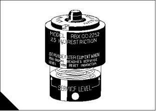
The air filter is fitted with a restriction indicator (A) which gives a visual warning when the filter needs a service.
When the red warning indicator is seen through the clear panel after the engine has stopped, the air filter
element must be renewed.
After a clean element has been fitted, press the reset button on the restriction indicator.
Environmental conditions have an important effect on the frequency at which the air filter needs to be serviced.
A
User’s Handbook, TSD3454E, Issue 2
17
This document is printed from SPI². Not for RESALE
![]()
![]()
4
2300 Series
How to check the amount of lubricating oil
Warning! Hot oil and hot components can cause personal injury. Do not allow hot oil or hot components to
contact the skin.
At the periods given in the service schedule use the dipstick to check the amount of lubricating oil in the sump.
1 Check the oil level with the engine stopped. The level must be maintained between the “L” mark and “H”
mark on the dipstick.
2 If necessary, remove the oil filler cap and add more oil of the same grade and specification as that which is
already in the system. Do not overfill.
3 Clean and fit the oil filler cap.
How to drain the primary fuel filter
At the periods given in the service schedule, the bowl of the primary fuel filter must be checked and, if
necessary, drained.
1 Open the drain; the drain is self-ventilated. Use a suitable container to collect the water drained from the
filter housing. Dispose of the water safely.
2 Close the drain. Tighten the drain valve securely to prevent air from entering the fuel system.
18
User’s Handbook, TSD3454E, Issue 2
This document is printed from SPI². Not for RESALE
![]()
![]()
4
2300 Series
Visual inspection
A visual inspection should take only a few minutes and can prevent costly repairs and accidents.
For maximum engine life, inspect the engine compartment before the engine is started. Look for items such
as oil or coolant leaks, loose fastenings, worn belts or loose connections. Repair as necessary.
The guards must be at the correct positions. Repair damaged guards or renew missing guards.
Wipe all caps and plugs before the engine is serviced to reduce the chance of system contamination.
For any type of leak (coolant, lubricating oil or fuel), clean away the fluid. If a leak is observed, find the
source and correct the leak. If a leak is suspected, check the fluid levels frequently until the leak is found
and repaired.
Accumulated grease and/or oil on an engine is a fire hazard. Remove it by steam cleaning or by the use of
a high pressure water jet.
Ensure that the coolant pipes are fitted correctly and that they are secure. Check for leaks. Check the
condition of all pipes.
Inspect the coolant pump for leaks.
Note: The coolant pump seal is lubricated by the coolant in the coolant system. It is normal for a small amount
of leakage to occur as the engine cools and the parts contract.
Excessive coolant leakage may indicate the need to renew the coolant pump seal. For the removal of the
coolant pump and the installation of the coolant pump and/or coolant pump seals, refer to the Workshop
Manual.
Inspect the lubrication system for leaks at the front crankshaft seal, the rear crankshaft seal, the sump, the
oil filter and the rocker cover. If many oil leaks are present, particularly on an old engine, there could be a
blockage of the engine breather.
Inspect the fuel system for leaks. Check for loose fuel line clamps or for loose ties on the fuel lines.
Inspect the ducts for the air inlet system and the elbows for cracks. Check also for loose clamps and check
the condition of mounting rubbers. Ensure that hoses and tubes are not in contact with other hoses, tubes,
wiring harnesses, etc.
Inspect the fan belts and the alternator belt for cracks, breaks or other damage. Where more than one belt
is used between two pulleys, all of the belts must be renewed together. Maximum belt life will only be
obtained if the belts are maintained at the correct tension.
Drain the water and sediment from fuel tanks on a daily basis to ensure that only clean fuel enters the fuel
system.
Inspect the wiring and the wiring harnesses for loose connections and for worn or frayed wires.
Inspect the earth strap for a good connection and for good condition.
Inspect the ECM-to-cylinder head earth strap for a good connection and for good condition.
Disconnect any battery chargers which are not protected against the current drain of the starter motor.
Check the condition and the electrolyte level of the batteries, unless the engine is fitted with a maintenance
free battery.
Check the condition of the gauges. Renew any gauges that are cracked. Renew any gauge that cannot be
calibrated.
User’s Handbook, TSD3454E, Issue 2
19
This document is printed from SPI². Not for RESALE
![]()
![]()
![]()
![]()
![]()
![]()
![]()
![]()
![]()
![]()
![]()
![]()
![]()
![]()
![]()
![]()
![]()
![]()
![]()
![]()
4
2300 Series
Diagnostics check
At the periods specified in the service schedule, use the Perkins Electronic Service Tool to retrieve the
diagnostic codes. A key to the codes is given below. Refer to the relevant Diagnostic Manual for further details.
Diagnostic codes
CID-FMI
1-11
Diagnostic code description
Injector cylinder No. 1 fault
Injector cylinder No. 2 fault
Injector cylinder No. 3 fault
Injector cylinder No. 4 fault
Injector cylinder No. 5 fault
Injector cylinder No. 6 fault
2-11
3-11
4-11
5-11
6-11
41-03
8 volt Sensor power supply open/short to B+
8 volt Sensor power supply short to ground
PWM Speed control abnormal
41-04
91-08
100-03
100-04
110-03
110-04
168-02
172-03
172-04
174-03
174-04
190-02
190-09
190-11, 12
248-09
253-02
254-12
261-13
262-03
262-04
268-02
273-03
273-04
274-03
274-04
281-03
281-04
281-05
282-03
282-04
285-03
285-04
286-03
286-04
286-05
323-03
323-04
323-05
Engine oil pressure sensor open/short to B+
Engine oil pressure sensor short to ground
Engine coolant temp sensor open/short to B+
Engine coolant temp sensor short to ground
Intermittent battery power to the ECM
Intake manifold temperature sensor open/short to B+
Intake manifold temperature sensor short to ground
Fuel temperature sensor open/short to B+
Fuel temperature sensor short to ground
Engine speed sensor data intermittent
Engine speed sensor abnormal update
Engine speed sensor mechanical fault
Perkins data link communications abnormal
Check customer or system parameters
ECM Fault
Engine timing calibration required
5 volt Sensor power supply open/short to B+
5 volt Sensor power supply short to ground
Check programmable parameters
Turbo outlet pressure sensor open/short to B+
Turbo outlet pressure sensor short to ground
Atmospheric pressure sensor open/short to B+
Atmospheric pressure sensor short to ground
Action alert lamp open/short to B+
Action alert lamp short to ground
Action alert lamp open circuit
Engine overspeed lamp open/short to B+
Engine overspeed lamp short to ground
Engine coolant temperature lamp open/short to B+
Engine coolant temperature lamp short to ground
Engine lubricating oil pressure lamp open/short to B+
Engine lubricating oil pressure lamp short to ground
Engine lubricating oil pressure lamp open circuit
Engine shutdown lamp open/short to B+
Engine shutdown lamp short to ground
Engine shutdown lamp open circuit
20
User’s Handbook, TSD3454E, Issue 2
This document is printed from SPI². Not for RESALE
![]()
![]()

4
2300 Series
CID-FMI
324-03
Diagnostic code description
Engine warning lamp open/short to B+
324-04
Engine warning lamp short to ground
Engine warning lamp open circuit
Engine speed sensor No. 2 data intermittent
Engine speed sensor No. 2 mechanical fault
Crank terminate relay open/short to B+
Service tool fault
324-05
342-02
342-11, 12
443-03
799-12
1266-03
1266-04
1690-8
Diagnostic lamp open/short to B+
Diagnostic lamp short to ground
Analogue throttle signal abnormal
User’s Handbook, TSD3454E, Issue 2
21
This document is printed from SPI². Not for RESALE
![]()
![]()

4
2300 Series
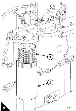
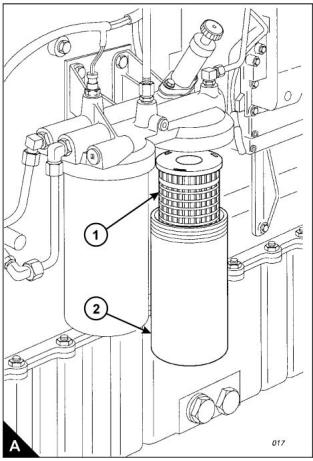
How to renew the element of the primary fuel filter
Cautions:
Do not allow dirt to enter the fuel system. Clean thoroughly the area around a fuel system component that
will be disconnected. Fit a suitable cover to any disconnected component of the fuel system.
Do not loosen fuel pipes or fittings except where indicated in this handbook.
1 Stop the engine. Turn the start switch to the “OFF” position. Disconnect the battery.
2 Close the fuel tank supply valve. Remove the drain plug from the base of the filter housing (A2) and drain
the water and fuel into a suitable container. Dispose of the mixture safely.
3 Remove the filter housing, remove the ‘O’ ring seal from the housing and withdraw the filter element (A1).
Warning! Discard the used filter element and ‘O’ ring seal in a safe place and in accordance with local
regulations.
4 Clean the inside of the housing and the housing thread with clean fuel oil and clean the contact face of the
filter head. Clean the drain plug and fit it to the housing.
Notes:
If a degreasing agent has been used to clean the housing, a special lubricant, CV60896, must be applied
to the threads before the housing is fitted.
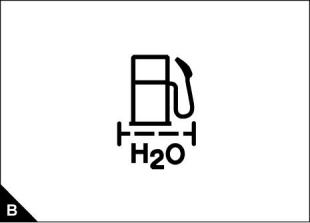
The correct filter element will be marked with the symbol shown (B).
Continued
22
User’s Handbook, TSD3454E, Issue 2
This document is printed from SPI². Not for RESALE
![]()
![]()
![]()
![]()
![]()
![]()
4
2300 Series
5 Fit a new element (A1) into the housing (A2), ensure that it engages fully with the guide in the base of the
housing. Fit a new ‘O’ ring seal to the top of the housing.
Cautions:
It is important that only genuine Perkins parts are used. The use of wrong parts could damage the fuel
injection equipment.
Do not fill the primary fuel filter with fuel before installation. The fuel would not be filtered and could be
contaminated. Contaminated fuel will cause accelerated wear to components of the fuel system.
6 Fit the housing onto the filter head. Tighten the housing to a torque of 80 Nm (59 lbf ft). Do NOT overtighten.
Ensure that the drain plug is tightened securely.
7 Clean away any fuel which has been spilled.
8 Open the fuel tank supply valve and eliminate air from the fuel system as given in "How to eliminate air from
the fuel system" on page 48.
9 Check for leaks.
User’s Handbook, TSD3454E, Issue 2
23
This document is printed from SPI². Not for RESALE
![]()
![]()
![]()
![]()

4
2300 Series
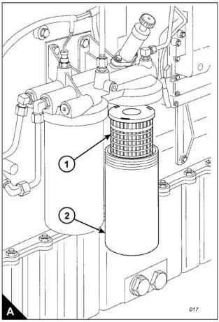
How to renew the element of the secondary fuel filter
Cautions:
Do not allow dirt to enter the fuel system. Clean thoroughly the area around a fuel system component that
will be disconnected. Fit a suitable cover to any disconnected component of the fuel system.
Do not loosen fuel pipes or fittings except where indicated in this handbook.
1 Stop the engine.
2 Turn the start switch to the “OFF” position. Disconnect the battery.
3 Close the fuel tank supply valve. Remove the drain plug from the base of the filter housing (A2) and drain
the fuel into a suitable container.
4 Remove the filter housing, remove the ‘O’ ring seal from the housing and withdraw the filter element (A1).
Warning! Discard the used filter element and ‘O’ ring seal in a safe place and in accordance with local
regulations.
5 Clean the inside of the housing and the housing thread with clean fuel oil and clean the contact face of the
filter head. Clean the drain plug and fit it to the housing.
Notes:
If a degreasing agent has been used to clean the housing, a special lubricant, CV60896, must be applied
to the threads before the housing is fitted.
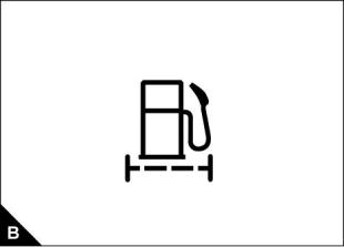
The correct filter element will be marked with the symbol shown (B).
Continued
24
User’s Handbook, TSD3454E, Issue 2
This document is printed from SPI². Not for RESALE
![]()
![]()
![]()
![]()
![]()
![]()
4
2300 Series
6 Fit a new element (A1) into the housing (A2), ensure that it engages fully with the guide in the base of the
housing. Fit a new ‘O’ ring seal to the top of the housing.
Cautions:
It is important that only genuine parts are used. The use of wrong parts could damage the fuel injection
equipment.
Do not fill the secondary fuel filter with fuel before installation. The fuel would not be filtered and could be
contaminated. Contaminated fuel will cause accelerated wear to components of the fuel system.
7 Fit the housing onto the filter head. Tighten the housing to a torque of 80 Nm (59 lbf ft). Do NOT overtighten.
Ensure that the drain plug is tightened securely.
8 Clean away any fuel which has been spilled.
9 Open the fuel tank supply valve and eliminate air from the fuel system as given in "How to eliminate air from
the fuel system" on page 48.
10 Check for leaks.
User’s Handbook, TSD3454E, Issue 2
25
This document is printed from SPI². Not for RESALE
![]()
![]()
![]()
![]()
4
2300 Series
How to check the specific gravity of the coolant
Warning! Do not remove the radiator cap while the engine is still hot and the system is under pressure
because dangerous hot coolant can be discharged.
Drain some coolant from the coolant system after the engine has been stopped and before the formation of
sediment. Proceed as follows:
1 For mixtures which contain inhibited ethylene glycol:
Put a hydrometer, and a reliable thermometer, into the antifreeze mixture and check the readings on both
instruments.
Compare the readings obtained with the chart and adjust the strength of the mixture as necessary.
2 For mixtures which contain inhibited propylene glycol:
Open the cover of the refractometer, check that the clear panel is clean and use a small syringe to apply
three or four drops of the coolant mixture to the clear panel.
Spread the coolant over the full area of the clear panel and close the cover. Hold the refractometer
horizontally with the clear panel at the top and inspect the sample through the viewer.
Compare the reading with the chart in the instructions; adjust the strength of the mixture as necessary.
Caution: The clear panel must be cleaned thoroughly before use. Some of the fluid which was tested earlier
can remain on the clear panel and this will affect the reading of the sample.
Protection against frost is as follows:
Antifreeze/water
(% by volume)
Protection down to
(°C)
50/50
60/40
-35
-40
A
40
45 50 55 60
60
50
40
30
140
122
104
C
D
86
68
50
20
10
0
1.04
1.05
1.06
1.07
1.08
1.09
1.10 1.11
B
Specific gravity chart
A = Percentage anti-freeze by volume
B = Specific gravity
C = Mixture temperature in Centigrade
D = Mixture temperature in Fahrenheit
26
User’s Handbook, TSD3454E, Issue 2
This document is printed from SPI². Not for RESALE
![]()
![]()
![]()
![]()
![]()
![]()
![]()

4
2300 Series
How to obtain an oil sample
Warning! Hot oil and hot components can cause personal injury. Do not allow hot oil or hot components to
contact the skin.
This operation must only be performed by personnel with the correct training. To avoid contamination of the
oil sample, ensure that the tools and equipment used are clean.
An oil sample kit (part number KRP1572), which includes the relevant sample bottles, is available from Perkins
dealers. Certain engines are fitted with an oil sample valve, use the relevant procedure given below.
Engines fitted with an oil sample valve
1 Fit the vented cap to the sample bottle and insert the open end of the tube into the one of the holes in the cap.
Warning! Hot oil under pressure is present at the oil sample valve. Protective clothing must be worn during
this operation. Do not allow hot oil or hot components to contact the skin.
2 With the engine running at the normal temperature of operation, remove the dust cap from the sample valve
on the engine and insert the nozzle of the tube into the sample valve. Press the nozzle against the valve, the
valve will open and allow the oil to flow. Ensure that the sample bottle remains upright and withdraw the nozzle
when the correct amount of oil is obtained; a mark on the bottle indicates the correct level for the oil sample.
3 Fit the dust cap to the sample valve.
4 Remove the vented cap from the sample bottle and fit the sealed cap. Dispose of the tube, nozzle and vented
cap in accordance with local regulations.
5 Complete the adhesive label and attach it to the sample bottle. Send the oil sample to a reputable oil analysis
laboratory to provide a recommendations report.
Engines without an oil sample valve
1 Run the engine until the normal temperature of operation is achieved, stop the engine and proceed with the
operation immediately.
2 Use a vacuum pump and a long flexible tube: remove the engine oil dipstick, insert the flexible tube into the
dipstick tube and withdraw the oil sample. Fit the dipstick to the dipstick tube.
3 Complete an adhesive label and attach it to the sample bottle. Send the oil sample to a reputable oil analysis
laboratory to provide a recommendations report.
4 Ensure that all equipment used is cleaned or, if relevant, disposed of in accordance with local regulations.
User’s Handbook, TSD3454E, Issue 2
27
This document is printed from SPI². Not for RESALE
![]()
![]()
4
2300 Series
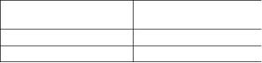
How to renew the engine lubricating oil
Warning! Hot oil and hot components can cause personal injury. Do not allow hot oil or hot components to
contact the skin.
1 Operate the engine until it is warm, then stop the engine.
2 A drain plug is fitted to both sides of the sump, remove one of the sump drain plugs (A1) and drain the
lubricating oil into a suitable container. Clean the drain plug and fit a new sealing washer. Fit the drain plug
and tighten it to a torque of 45 Nm (33 lbf ft).
Warning! Discard the used filter element and used engine oil in a safe place and in accordance with local
regulations.
3 Renew the element of the lubricating oil filter as given in "How to renew the element of the lubricating oil
filter" on page 29.
4 Clean the area around the oil filler cap (B1) and remove the cap. Fill the sump to the “H” mark on the dipstick
(B2) with clean new lubricating oil of the correct grade as given in "Lubricating oil specification" on page 50.
Do NOT overfill.
To prevent damage to the crankshaft bearings, crank the engine with the fuel OFF. This will fill the oil filters
before the engine is started. Do NOT crank the engine continuously for more than 30 seconds. Ensure that oil
pressure is indicated on the oil pressure gauge, or the service tool, before the engine is started.
5 Operate the engine at low idle speed for two minutes and check for leakage from the oil filter assembly.
6 Stop the engine and allow the oil to drain back to the sump for a minimum of ten minutes. Check the oil level
on the dipstick and, if necessary, add more oil. The oil level must be between the “L” and “H” marks on the
dipstick.
28
User’s Handbook, TSD3454E, Issue 2
This document is printed from SPI². Not for RESALE
![]()
![]()
4
2300 Series
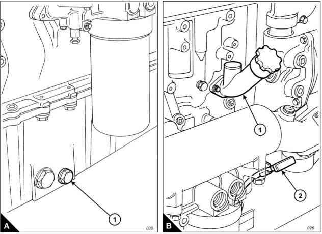
How to renew the element of the lubricating oil filter
1 Stop the engine.
2 Turn the start switch to the “OFF” position. Disconnect the battery.
3 Remove the drain plug (A2) from the base of the oil filter housing (A1) and drain the oil into a suitable
container.
4 Remove the filter housing, remove the ‘O’ ring seal from the housing and withdraw the filter element.
Warning! Discard the used filter element, ‘O’ ring seal and used engine oil in a safe place and in accordance
with local regulations.
5 Clean the housing and clean the contact face of the filter head. Clean the drain plug (A2) and fit it to the
housing.
Note: If a degreasing agent has been used to clean the housing, a special lubricant, CV60896, must be applied
to the threads before the housing is fitted.
6 Fit a new element into the housing, ensure that it engages fully with the guide in the base of the housing. Fit
a new ‘O’ ring seal around the top of the housing.
Caution: It is important that only genuine Perkins parts are used. The use of incorrect parts could damage the
engine. The correct filter element will be marked with the symbol shown (B).
7 Fit the housing onto the filter head and tighten by use of a socket and torque wrench on the hexagon (A1).
Tighten the housing to a torque of 80 Nm (59 lbf ft). Do NOT overtighten. Ensure that the drain plug is tightened
securely.
8 Check the amount of engine oil in the sump. If necessary, add more oil of the correct grade and specification.
Refer to "Lubricating oil specification" on page 50.
9 Run the engine and check for leaks.
User’s Handbook, TSD3454E, Issue 2
29
This document is printed from SPI². Not for RESALE
![]()
![]()
免费热线
400-100-8969 15088860848
400-100-8969 15088860848
机组销售
0574-26871589 15267810868
0574-26871589 15267810868
配件销售
0574-26886646 15706865167
0574-26886646 15706865167
维修热线
0574-26871569 18658287286
0574-26871569 18658287286
手机端

微信公众号