 English
 Espaol
 Franais
 阿拉伯
阿拉伯 中文(简)
中文(简) Deutsch
 Italiano
 Português
 日本
日本 韩国
韩国 български
 hrvatski
 esky
esky Dansk
Dansk Nederlands
 suomi
suomi Ελληνικ
 印度
印度 norsk
norsk Polski
 Roman
Roman русский
 Svenska
 约翰迪尔强鹿柴油机气缸体前板的拆卸方法与惰轮衬套和轴的测量,约翰迪尔强鹿柴油机气缸体前板的拆卸方法与惰轮衬套和轴的测量技术支持,约翰迪尔强鹿柴油机气缸体前板的拆卸方法与惰轮衬套和轴的测量费用,约翰迪尔强鹿柴油机气缸体前板的拆卸方法与惰轮衬套和轴的测量服务中心,约翰迪尔强鹿柴油机气缸体前板的拆卸方法与惰轮衬套和轴的测量价格规格资料查询,约翰迪尔强鹿柴油机气缸体前板的拆卸方法与惰轮衬套和轴的测量哪里有,约翰迪尔强鹿柴油机气缸体前板的拆卸方法与惰轮衬套和轴的测量多少钱,约翰迪尔强鹿柴油机气缸体前板的拆卸方法与惰轮衬套和轴的测量附近联系电话,宁波日昕动力科技有限公司

约翰迪尔强鹿柴油机气缸体前板的拆卸方法与惰轮衬套和轴的测量
详细描述
John Deere约翰迪尔强鹿柴油机气缸体前板的拆卸方法与惰轮衬套和轴的测量
Before the front plate can be removed, the following components must first be removed:
· Timing gear cover. (See REMOVE TIMING GEAR COVER in this group.)
· Timing Wheel. (See REMOVE AND INSTALL
CRANKSHAFT TIMING WHEEL (TWO-VALVE HEAD ENGINES WITH VP44 OR DE10 FUEL INJECTION PUMPS AND ALL FOUR-VALVE HEAD ENGINES in Group 040.)
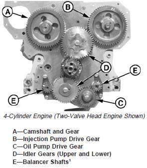
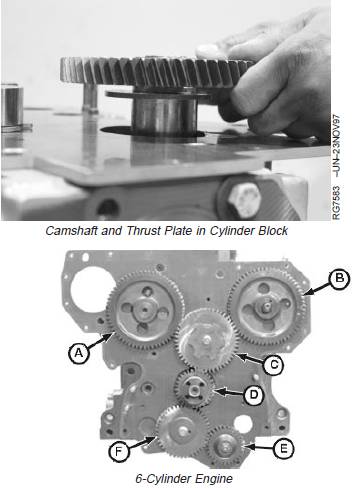
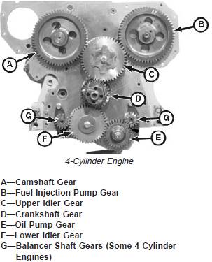
· Camshaft and gear (A). (See REMOVE CAMSHAFT in this group.)
· Injection pump drive gear (B) and injection pump. See Section 02, Group 090 of CTM207 (Mechanical Fuel Systems), CTM170 (Level 4 Electronic Fuel Systems), CTM331 (Level 12 Electronic Fuel Systems), CTM284 (Level 1 Electronic Fuel Systems) or CTM220 (Level 11Electronic Fuel Systems with Denso High PressureCommon Rail).
· Oil pump drive gear (C) and oil pump. (See REMOVEENGINE OIL PUMP in Group 060.)
· Idler gears (D)
· Balancer shafts (E)1 (See REMOVE BALANCERSHAFTS in this group.)
· Oil pressure regulating valve, if equipped with cartridgetype. (See REMOVE AND INSTALL OIL PRESSUREREGULATING VALVE in Group 060.)
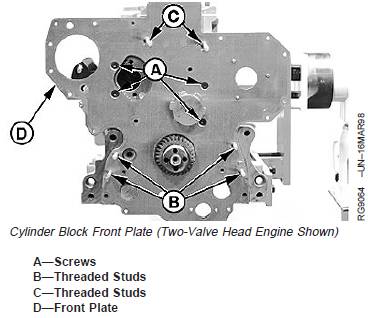
1. Remove four countersunk, TORXâ screws (A) from gear and oil pump using T-40 TORXâ adapter.
NOTE: On earlier engines1, there are two countersunk TORXâ screws used in place of threaded studs(C). On four-valve head engines, double ended studsare used to hold the fuel injection pump andtiming gear cover. Remove if needed.
2. Remove six threaded studs (B) and (C) using E-8TORXâ Socket.
3. Remove front plate (D).
TORX is a registered trademark of Camcar/Textron1 Serial Numbers: Dubuque-built engines ( —703904), Saran-builtengines ( —516217), Torreon-built engines (does not apply).
4. Remove oil bypass valve and spring.
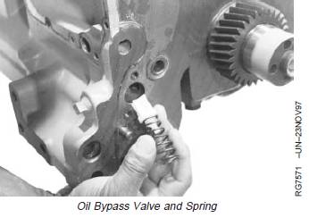
IMPORTANT: All surfaces must be free of oil and dirt.
5. Thoroughly clean front face of cylinder block.
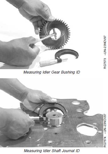
John Deere约翰迪尔强鹿柴油机惰轮衬套和轴的测量与标准值参数
1. Measure idler gear bushing ID and shaft OD todetermine oil clearance. If oil clearance exceedsspecification, replace worn parts.
Specification
Upper Idler Gear Bushing(Two-Valve Head Engine) (30mm Wide Gear)—ID 69.802—69.832 mm(2.7481—2.7493 in.)
Upper Idler Gear Bushing(Two-Valve Head Engine) (22mm Wide Gear)—ID 44.49—44.54 mm(1.751-1.753 in.)
Upper Idler Gear Bushing(Four-Valve Head Engine)—ID 92.732—92.762 mm(3.6509—3.6520 in.)
Lower Idler Gear Bushing—ID 44.489—44.539 mm(1.7515—1.7535 in.)
Upper Idler Gear Shaft(Two-Valve Head Engine) (30mm Wide Gear)—OD 69.757—69.777 mm(2.7463—2.7471 in.)
Upper Idler Gear Shaft(Two-Valve Head Engine) (22mm Wide Gear)—OD 44.43—44.46 mm(1.749-1.750 in.)
Upper Idler Gear Shaft(Four-Valve Head Engine)—OD 92.687—92.707 mm(3.6491—3.6499 in.)
Lower Idler Gear Shaft—OD 44.437—44.463 mm(1.7495—1.7505 in.)
Upper Idler GearBushing-to-Shaft (Two-ValveHead Engine)—Oil Clearance 0.075—0.125 mm(0.0030—0.0049 in.)
Upper Idler GearBushing-to-Shaft (Four-ValveHead Engine)—Oil Clearance 0.0025—0.075 mm(0.0010—0.0030 in.)
Lower Idler GearBushing-to-Shaft—Oil Clearance 0.026—0.102 mm(0.0010—0.0040 in.)
Upper Idler Gear—End Play 0.070—0.170 mm(0.0027—0.0066 in.)
Lower Idler Gear—End Play 0.070—0.330 mm(0.0027—0.0129 in.)
2. If idler gear end play, measured earlier in this group,was out of specification, remove idler shaft and thrustwasher from front plate. (See REMOVE LOWER ANDUPPER IDLER SHAFTS, later in this group.)
3. Check thrust washer for wear.
4. Measure idler gear hub width and shaft width. Replace worn parts that are out of specification.
John Deere约翰迪尔强鹿柴油机时间平衡器轴的安装与标准值参数
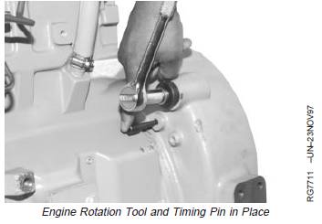
1. Using JDE81-1 or JDE83 Flywheel Turning Tool andJDG1571 or JDE81-4 Timing Pin, lock No. 1 piston atTDC compression stroke.
2. Lubricate balancer shaft bushings and journals with clean engine oil.
IMPORTANT: Balancer shafts MUST BE installed in the location from which removed. Reversing shaft locations could result in excessive bushing and shaft wear. If in doubt about proper shaft locations, replace the balancer shaft and bushings.
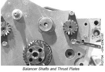
3. Install balancer shafts and thrust plates. Tighten thrust plate cap screws to specifications.
Specification
Balancer Shaft Thrust Plate Cap Screws—Torque........................................................... 40 N•m (29.5 lb-ft)
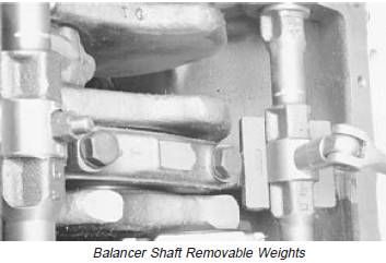
4. Later engines1 have balancer shafts with removable weights. Install weights to balancer shafts using new cap screws and nuts. Tighten to specifications.
Specification
Balancer Shaft Removable
Weights (One-Bolt Weights)— Torque ............................................................................. 58 N•m (43 lb-ft)
Balancer Shaft Removable
Weights (Two-Bolt Weights)—Torque ............................................................................. 40 N•m (30 lb-ft)
1Serial Numbers: Dubuque-built engines (700877— ), Saran-built engines (500212— ), Torreon-built engines (001000— ).
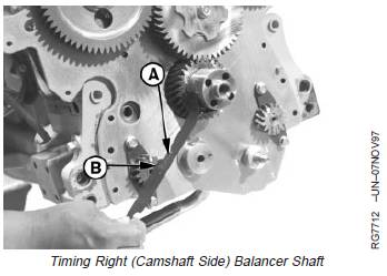
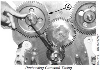
5. Turn right (camshaft side) balancer shaft so timingmark on gear is aligned with JD254A (JD-254A) TimingTool (A). Timing mark on balancer shaft gear mustpoint to centerline of crankshaft when correctly timed.
NOTE: Keyway (B) in balancer shaft gear will be at 12o’clock position, when engine is locked at No. 1TDC compression.
6. Apply TY6333 High-Temperature Grease to idler gearbushing ID and shaft OD. Install lower idler gearwithout turning balancer shaft.
A—Timing Tool
B—Keyway
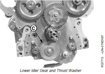
NOTE: Install thrust washer with “X” mark facing away from gear.
7. Install thrust washer over lower idler gear (C) and shaft.
8. Lubricate and install cap screw through idler shaft into threaded leg of oil pump housing and finger tighten only.
C—Lower Idler Gear
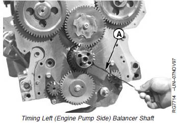
9. Turn left (injection pump side) balancer shaft so timing mark on gear is aligned with JD254A (JD-254A) Timing Tool (A).
10. Install oil pump gear. Finger tighten gear retaining nut.
11. Recheck gear timing for both balancer shafts
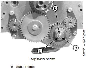
12. Tighten oil pump drive gear retaining nut to specifications. Stake nut to shaft in three places (B). (See INSTALL ENGINE OIL PUMP in Group 060 for oil pump installation.)
Specification
Oil Pump Drive Gear Staked
Nut—Torque .................................................................... 50 N•m (37 lb-ft)
13. Tighten lubricated lower idler gear cap screws to specifications.
Specification
Lower Idler Gear Cap Screw (Lubricated Threads)—Torque ........................................ 70 N•m (53 lb-ft)
John Deere约翰迪尔强鹿柴油机凸轮轴的安装与技术参数规范
1. Using JDE81-1 or JDE83 Flywheel Turning Tool and JDG1571 or JDE81-4 Timing Pin, lock No. 1 piston at TDC compression stroke.
NOTE: Injection pumps must be properly installed and timed during camshaft installation. For Stanadyne and Delphi/Lucas rotary pumps, see appropriate pump installation procedure in Section 02, Group 090 of CTM207 (MechanicalFuel Systems).
For Denso In-Line pumps, see appropriate pump installation procedure in Section 02, Group 090 of CTM220 (Level 11 Electronic Fuel Systems with Denso High Pressure Common Rail). For static lock-pin timing of Bosch VP44 pumps,
see BOSCH VP44 ROTARY INJECTION PUMP TIMING in Section 02, Group 90 of CTM170 (Level 4 Electronic Fuel Systems). Then, see
INSTALL BOSCH VP44 FUEL INJECTION PUMP in Section 02, Group 090 of CTM170 (Level 4 Electronic Fuel Systems).
For static lock-pin timing of Denso and Motorpal pumps, see DENSO AND MOTORPAL IN-LINE INJECTION PUMP TIMING in Section 02, Group 090 of CTM207 (Mechanical Fuel Systems). Then, see the appropriate pump installation procedure in Section 02, Group 090 of CTM207 (Mechanical Fuel Systems).
For static lock-pin timing of Stanadyne DE10 pumps, see INJECTION PUMP STATIC TIMING in Section 02, Group 090 of CTM331 (Level 12 Electronic Fuel Systems).
For static timing of Delphi/Lucas DP201 pumps,see FUEL INJECTION PUMP TIMING in Section 02, Group 090 of CTM284 (Level 1 Electronic Fuel Systems).
2. Install fuel injection pump and drive gear. See appropriate reference as identified in NOTE above.
3. Lubricate camshaft bearing journals, lobes, and followers with TY6333 High-Temperature Grease.
IMPORTANT: DO NOT allow camshaft lobes to drag on camshaft bore or bushing surfaces while installing camshaft. Bearing surfaces may become scratched or scored. Rotate camshaft during installation to avoid obstruction in any bore.
4. Install camshaft and thrust plate in cylinder block. Be careful not to damage bushing ID.
5. Install thrust plate cap screws and tighten to specifications.
Specification
Camshaft Thrust Plate Cap
Screws—Torque.............................................................. 35 N•m (26 lb-ft)
6. On Two-Valve Head Engine:
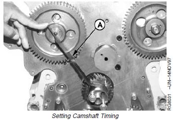
a. With JD254A (JD-254A) Timing Tool resting on nose of crankshaft and center of camshaft (as shown), turn camshaft until timing mark (A) on camshaft gear aligns with timing tool.
A—Timing Mark
NOTE: Denso, Motorpal, Bosch VP44 and Stanadyne
DE10 injection pumps are static lock-pin timed
during installation. The following step applies to
earlier Stanadyne and to all Delphi/Lucas Pumps
only.
IMPORTANT: Use the timing mark corresponding to
the number of cylinders the engine has
that is being timed.
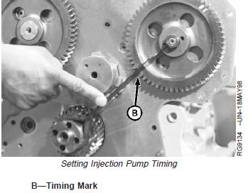
b. On earlier Stanadyne and all Delphi/Lucas rotary
pumps: Check injection pump gear timing with
JD254A (JD-254A) Timing Tool resting on nose of
crankshaft and center of injection pump shaft.
Timing mark (B) on injection pump drive gear, as
described in table below, must align with timing tool
(as shown).
INJECTION PUMP GEAR TIMING MARKS
Injection Pump Model Timing Mark
Delphi/Lucas and Stanadyne 4-Cyl. Engine ........... 4
Stanadyne 6-Cyl. Engine ........................................ S6
Delphi/Lucas 6-Cyl. Engine .................................... L6
Delphi/Lucas (1st Production 1170 Combines) ...... L6
Delphi/Lucas (Early 1170 Combines) ..................... 6C
Delphi/Lucas (Late 1170 Combines) ...................... 6Z
IMPORTANT: To ensure proper lubrication of new
upper idler gear bushing and camshaft
bushing, install new upper idler gear
with the reference number facing away
from engine.
c. Lubricate upper idler gear bushing ID and shaft OD
with TY6333 High-Temperature Grease. Using
JDG791A Idler Gear Installer Pilot,1 install idler gear
without turning camshaft gear or injection pump
gear.
NOTE: Install thrust washer with “X” mark facing away
from gear.
d. Lubricate upper idler gear cap screw threads with oil.
Install upper idler gear thrust washer and cap screw.
Tighten cap screw to specifications.
Specification
Upper Idler Gear Cap Screw—
Torque ............................................................................. 70 N•m (53 lb-ft)
e. Recheck camshaft gear (A) and injection pump drive
gear timing to make sure they are correct.
A—Camshaft Gear
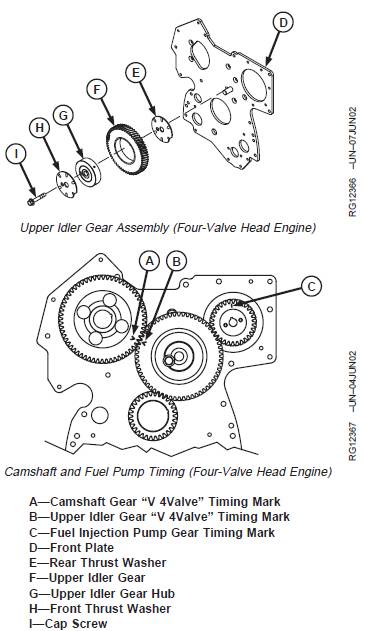
7. On Four-Valve Head Engine:
a. Align the fuel injection pump gear timing mark (C) to
the twelve o’clock position.
b. Install upper idler gear rear thrust washer (E) with
side marked “X” facing the front plate (D).
c. Lubricate upper idler gear hub ID and shaft OD with
TY6333 High-Temperature Grease. Install upper
idler gear hub (G).
IMPORTANT: To ensure proper lubrication of new
upper idler gear bushing and camshaft
bushing, install new upper idler gear
with the reference number facing away
from engine.
Gears must have “V 4Valve” marking.
Use straight edge to align timing marks
with shaft center lines.
d. Lubricate upper idler gear ID and upper idler gear
hub OD with TY6333 High Temperature Grease.
Install upper idler gear (F) with timing ribs toward
the front plate. Using straightedge, align camshaft
gear “V 4Valve” timing mark (A) with upper idler
gear “V 4Valve” timing mark (B). The “V” timing
marks must be facing each other and in line with
the centerline of the camshaft gear and the upper
idler gear.
e. Install upper idler gear front thrust washer (H) with
“X” side facing away from gear.
f. Lubricate upper idler gear cap screw (I) threads with
oil. Tighten cap screw to specifications.
Specification
Upper Idler Gear Cap Screw—
Torque ............................................................................. 70 N•m (53 lb-ft)
8. On All Engines: install timing wheel, if equipped. (See
REMOVE AND INSTALL CRANKSHAFT TIMING
WHEEL (TWO-VALVE HEAD ENGINES WITH VP44
OR DE10 INJECTION PUMP AND ALL FOUR-VALVE
HEAD ENGINES) in Group 040.)
Clean and Inspect Timing Gear Cover
1. Drive crankshaft front oil seal out of cover.
2. Remove material and sealant from cylinder block
and timing gear cover gasket surfaces. If
necessary, remove oil filler neck and gasket and
injection pump drive gear nut cover plate and
gasket.
CAUTION: Do not spin bearings when drying
with compressed air.
3. If engine is equipped with the auxiliary drive,
remove auxiliary drive as described earlier in this
group.
4. If engine is equipped with electronic tachometer
(magnetic pick-up) sensor, remove sensor and
O-ring. (See REMOVE AND INSTALL MAGNETIC
PICK-UP SENSOR, as described in this group.)
5. Clean timing gear cover in solvent. Dry with
compressed air.
6. Inspect cover for cracks or damage. Make sure seal
bore is clean and free of nicks.
免费热线
400-100-8969 15088860848
400-100-8969 15088860848
机组销售
0574-26871589 15267810868
0574-26871589 15267810868
配件销售
0574-26886646 15706865167
0574-26886646 15706865167
维修热线
0574-26871569 18658287286
0574-26871569 18658287286
手机端

微信公众号