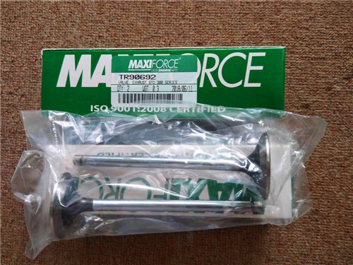
麦克福斯约翰迪尔发动机零配件
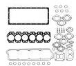
约翰迪尔 6081 高压缩活塞
|
|
|
发动机和设备型号
|
高压缩活塞
4801 4803
孔径:
4.56 in 116 mm
销径 Ø:
1.8742 in (+/- .0002) = 47 mm
发动机型号:
6081HDW08
6081HDW09
6081HDW13
6081HRW25
6081HRW31
6081HRW32
6081HRW33
6081HRW34
6081HRW41
6081HRW42
6081HRW43
6081HT002
6081HT008
6081HTJ05
6081HTJ06
6081HTJ07
6081HTJ08
6081HZ009
|
|
|
强鹿JOHN DEERE柴油机配件、发动机配件、发电机组:
T19044、RE62418、RE62419、RE521248、RE520842、C085004、RE509672、RE196945、RE191915、RE522688、RE522687、RE519774、RE532628、RE507980、RE531703、RE24619、RE187966、RE205726、RE507264、RE504836、RE509036、RE533910、RE532952、RE530107、RE508971
GRID PAGE GRID PAGE
A 9H23 AIR CONDITIONER COMPRESSOR (LOW MOUNT)
(USE W/ADJ FAN NO AUX DRIVE) (7406) 7400 - 7410
10D17 ACCESSORY PARTS (9901) 9900 - 9930 9I9 AIR CONDITIONER COMPRESSOR (LOW MOUNT)
9K9 ADAPTER KIT, AUX DRIVE 9 & 13 TOOTH, LH (USE W/ADJ FAN NO AUX DRIVE) (7412) 7400 - 7422
(9701) 9700 - 9704 9I15 AIR CONDITIONER COMPRESSOR (LOW MOUNT)
9K10 ADAPTER KIT, AUX DRIVE 9 & 9 TOOTH, LH (USE W/ADJ FAN NO AUX DRIVE) (7422) 7400 - 7428
(9701) 9700 - 9705 9I17 AIR CONDITIONER COMPRESSOR (LOW MOUNT)
8C15 ADJUSTABLE FAN DRIVE (2303) . 2300 - 2302 (USE W/ADJ FAN NO AUX DRIVE) (7426) 7400 - 7430
8C21 ADJUSTABLE FAN DRIVE (2307) (TF) .. 2300 - 2308 9J1 AIR CONDITIONER COMPRESSOR (LOW MOUNT)
8D10 ADJUSTABLE FAN DRIVE (2337) (TF) .. 2300 - 2322 (USE W/ADJ FAN NO AUX DRIVE) (7432) 7400 - 7438
8E13 ADJUSTABLE FAN DRIVE (2355) (TF) .. 2300 - 2350 9H17 AIR CONDITIONER COMPRESSOR (LOW MOUNT)
8E14 ADJUSTABLE FAN DRIVE (2356) (TF) .. 2300 - 2351 (USE W/ADJ FAN NO AUX DRIVE)(7402) 7400 - 7404
8E15 ADJUSTABLE FAN DRIVE (2357) (TF) .. 2300 - 2352 9H15 AIR CONDITIONER COMPRESSOR (LOW MOUNT)
8E16 ADJUSTABLE FAN DRIVE (2359) (TF) .. 2300 - 2353 (USE W/FIXED FAN NO AUX DRIVE) (7401)7400 - 7402
8E17 ADJUSTABLE FAN DRIVE (2359) (TF) .. 2300 - 2354 9I7 AIR CONDITIONER COMPRESSOR (LOW MOUNT)
7G16 AFTERCOOLER (1702) (AF).. 1700 - 1702 (USE W/FIXED FAN NO AUX DRIVE) (7411)7400 - 7420
7G21 AFTERCOOLER (1704) (AF).. 1700 - 1708 9I13 AIR CONDITIONER COMPRESSOR (LOW MOUNT)
7H1 AFTERCOOLER (1705) (AF).. 1700 - 1712 (USE W/FIXED FAN NO AUX DRIVE) (7421)7400 - 7426
7H5 AFTERCOOLER (1706) (AF).. 1700 - 1716 9I23 AIR CONDITIONER COMPRESSOR (LOW MOUNT)
7H9 AFTERCOOLER (1707) (AF).. 1700 - 1720 (W/FIXED FAN NO AUX DRIVE) (7431) 7400 - 7436
7H13 AFTERCOOLER (1708) (AF).. 1700 - 1724 9K15 AIR CONDITIONER COMPRESSOR KIT
7H17 AFTERCOOLER (1709) (AF).. 1700 - 1728 (ADJ FAN, NO AUX DRIVE) (9701) 9700 - 9710
7H21 AFTERCOOLER (1710) (AF).. 1700 - 1732 9K13 AIR CONDITIONER COMPRESSOR KIT
7H23 AFTERCOOLER (1711) (AF).. 1700 - 1734 (FIXED FAN, NO AUX DRIVE) (9701) 9700 - 9708
7I1 AFTERCOOLER (1712) (AF).. 1700 - 1736 9J5 AIR CONDITIONER COMPRESSOR, NO
7I3 AFTERCOOLER (1713) (AF).. 1700 - 1738 (7498) 7400 - 7442
7I5 AFTERCOOLER (1714) (AF).. 1700 - 1740 9K21 AIR GOVERNOR (9701) 9700 - 9716
7I7 AFTERCOOLER (1715) (AF).. 1700 - 1742 7G15 AIR INTAKE (1701) (HF) 1700 - 1701
7I9 AFTERCOOLER (1716) (AF).. 1700 - 1744 7G16 AIR INTAKE (1702) (AF) 1700 - 1702
7I11 AFTERCOOLER (1717) (AF).. 1700 - 1746 7G18 AIR INTAKE (1702) (HF) 1700 - 1704
7I13 AFTERCOOLER (1718) (AF).. 1700 - 1748 7G19 AIR INTAKE (1703) (TF) 1700 - 1706
7I17 AFTERCOOLER (1731) (AF).. 1700 - 1752 7G21 AIR INTAKE (1704) (AF) 1700 - 1708
7I20 AFTERCOOLER (1737) (AF).. 1700 - 1756 7G24 AIR INTAKE (1704) (HF) 1700 - 1711
9L6 AIR CLEANER (9701) (AF,TF) 9700 - 9726 7G23 AIR INTAKE (1704) (TF) 1700 - 1710
9L2 AIR CLEANER, HEAVY DUTY (9701) 9700 - 9722 7H1 AIR INTAKE (1705) (AF) 1700 - 1712
9L4 AIR CLEANER, LIGHT DUTY (9701) . 9700 - 9724 7H4 AIR INTAKE (1705) (HF) 1700 - 1715
9J16 AIR COMPRESSOR (HOLSET) (7804) 7800 - 7804 7H3 AIR INTAKE (1705) (TF) 1700 - 1714
9J17 AIR COMPRESSOR (HOLSET) (7804) 7800 - 7806 7H5 AIR INTAKE (1706) (AF) 1700 - 1716
9J19 AIR COMPRESSOR (HOLSET) (7805) 7800 - 7808 7H7 AIR INTAKE (1706) (TF) 1700 - 1718
9J20 AIR COMPRESSOR (HOLSET) (7805) 7800 - 7810 7H9 AIR INTAKE (1707) (AF) 1700 - 1720
9J13 AIR COMPRESSOR (MIDLAND) (7802).. 7800 - 7801 7H11 AIR INTAKE (1707) (TF) 1700 - 1722
9J14 AIR COMPRESSOR (MIDLAND) (7802).. 7800 - 7802 7H13 AIR INTAKE (1708) (AF) 1700 - 1724
9K19 AIR COMPRESSOR KIT (HOLSET) 7H15 AIR INTAKE (1708) (TF) 1700 - 1726
(9701) 9700 - 9714 7H17 AIR INTAKE (1709) (AF) 1700 - 1728
10C15 AIR COMPRESSOR KIT (MIDLAND) . 9900 - 9901 7H19 AIR INTAKE (1709) (TF) 1700 - 1730
9K17 AIR COMPRESSOR KIT (MIDLAND) 7H21 AIR INTAKE (1710) (AF) 1700 - 1732
(9701) 9700 - 9712 7H23 AIR INTAKE (1711) (AF) 1700 - 1734
9H19 AIR CONDITIONER COMPRESSOR (HIGH MOUNT) 7I1 AIR INTAKE (1712) (AF) 1700 - 1736
(USE W/ADJ FAN LH AUX DRIVE) (7403) 7400 - 7406 7I3 AIR INTAKE (1713) (AF) 1700 - 1738
9H21 AIR CONDITIONER COMPRESSOR (HIGH MOUNT) 7I5 AIR INTAKE (1714) (AF) 1700 - 1740
(USE W/ADJ FAN LH AUX DRIVE) (7405) 7400 - 7408 7I7 AIR INTAKE (1715) (AF) 1700 - 1742
9H24 AIR CONDITIONER COMPRESSOR (HIGH MOUNT) 7I9 AIR INTAKE (1716) (AF) 1700 - 1744
(USE W/ADJ FAN LH AUX DRIVE) (7407) 7400 - 7412 7I11 AIR INTAKE (1717) (AF) 1700 - 1746
9I1 AIR CONDITIONER COMPRESSOR (HIGH MOUNT) 7I13 AIR INTAKE (1718) (AF) 1700 - 1748
(USE W/ADJ FAN LH AUX DRIVE) (7408) 7400 - 7414 7I16 AIR INTAKE (1726) (HF) 1700 - 1751
9I3 AIR CONDITIONER COMPRESSOR (HIGH MOUNT) 7I15 AIR INTAKE (1726) (TF) 1700 - 1750
(USE W/ADJ FAN LH AUX DRIVE) (7409) 7400 - 7416 7I17 AIR INTAKE (1731) (AF) 1700 - 1752
9I5 AIR CONDITIONER COMPRESSOR (HIGH MOUNT) 7I19 AIR INTAKE (1733) (HF) 1700 - 1754
(USE W/ADJ FAN LH AUX DRIVE) (7410) 7400 - 7418 7I20 AIR INTAKE (1737) (AF) 1700 - 1756
9I11 AIR CONDITIONER COMPRESSOR (HIGH MOUNT) 7I22 AIR INTAKE (1738) (TF) 1700 - 1758
(USE W/ADJ FAN LH AUX DRIVE) (7418) 7400 - 7424 8I1 ALTERNATOR (12V 120AMP) (BOSCH) (3104) 3100 - 3104
9I19 AIR CONDITIONER COMPRESSOR (HIGH MOUNT) 8I2 ALTERNATOR (12V 95AMP) (BOSCH) (3105) .. 3100 - 3105
(USE W/ADJ FAN LH AUX DRIVE) (7428) 7400 - 7432 8I10 ALTERNATOR (12V-90AMP) (DENSO) (3143) .. 3100 - 3112
9I21 AIR CONDITIONER COMPRESSOR (HIGH MOUNT) 8H23 ALTERNATOR (12V, 140 AMP) (DENSO) (3101) .. 3100 - 3101
(USE W/ADJ FAN LH AUX DRIVE) (7429) 7400 - 7434 8H24 ALTERNATOR (12V, 200 AMP)
9J3 AIR CONDITIONER COMPRESSOR (HIGH MOUNT) (LEECE-NEVILLE) (3102) .. 3100 - 3102
(USE W/ADJ FAN LH AUX DRIVE) (7438) 7400 - 7440 8I6 ALTERNATOR (12V, 98 AMP) (DELPHI) (3140) 3100 - 3108
I-12 POWERTECH 8.1 L OEM ENGINE (ESN -199999) PC2527 (10-DEC-02)
8I7 ALTERNATOR (24V, 40 AMP) (DELPHI) (3142) 3100 - 3109 8L15 AUXILIARY DRIVE 9 & 9 TOOTH SPLINE
8I3 ALTERNATOR (24V, 60 AMP) (DENSO) (3106) 3100 - 3106 (5202) 5200 - 5204
8H25 ALTERNATOR (24V, 80 AMP) (BOSCH) (3103) 3100 - 3103 8L17 AUXILIARY DRIVE 9 & 9 TOOTH SPLINE
8I4 ALTERNATOR (3107) 3100 - 3107 (5203) 5200 - 5206
9D6 ALTERNATOR BRACKET (6204) 6200 - 6204 9K7 AUXILIARY DRIVE, LEFT HAND, BASE, KIT
9D8 ALTERNATOR BRACKET (6205) 6200 - 6206 (9701) 9700 - 9702
9D10 ALTERNATOR BRACKET (6206) 6200 - 6209 9K11 AUXILIARY DRIVE, RIGHT HAND KIT
9D11 ALTERNATOR BRACKET (6209) 6200 - 6210 (9701) 9700 - 9706
9D13 ALTERNATOR BRACKET (6213) 6200 - 6212
9D15 ALTERNATOR BRACKET (6215) 6200 - 6214
8I8 ALTERNATOR COMPONENTS (3142) B
(DENSO) (24V 40 AMP) 3100 - 3110
8H25 ALTERNATOR PULLEY (BOSCH) (3103) .. 3100 - 3103 8K7 BEARING CAPS, MAIN (4602) 4600 - 4602
8I1 ALTERNATOR PULLEY (BOSCH) (3104) .. 3100 - 3104 8K10 BEARING CAPS, MAIN (4603) (TF) 4600 - 4606
8I2 ALTERNATOR PULLEY (BOSCH) (3105) .. 3100 - 3105 8K13 BEARING CAPS, MAIN (4604) (AF) 4600 - 4610
8H23 ALTERNATOR PULLEY (DENSO) (3101) .. 3100 - 3101 8K17 BEARINGS, CRANKSHAFT AND DRIVE
8I3 ALTERNATOR PULLEY (DENSO) (3106) .. 3100 - 3106 GEAR (4701) 4700 - 4701
8H24 ALTERNATOR PULLEY (LEECE-NEVILLE) 8K18 BEARINGS, CRANKSHAFT AND DRIVE
(3102) 3100 - 3102 GEAR (4702) 4700 - 4702
9D4 ALTERNATOR SUPPORT (6202) 6200 - 6202 9D4 BELT TENSIONER (6202).. 6200 - 6202
9D5 ALTERNATOR SUPPORT (6203) 6200 - 6203 9D5 BELT TENSIONER (6203).. 6200 - 6203
8I5 ALTERNATOR W/TVP (12V, 200 AMP) (3108) 9D6 BELT TENSIONER (6204).. 6200 - 6204
(LEECE-NEVILLE) (AF,HF) 3100 - 3107A 9D8 BELT TENSIONER (6205).. 6200 - 6206
10D4 AMMETER GAUGE 9900 - 9916 9D10 BELT TENSIONER (6206).. 6200 - 6209
10D4 AMMETER, GAUGE9900 - 9916 9D11 BELT TENSIONER (6209).. 6200 - 6210
2D23 ANEROID ACTIVATOR, HYDRAULIC 9D13 BELT TENSIONER (6213).. 6200 - 6212
(1602) (AF,TF,HF) .. 1600 - 1630 9D15 BELT TENSIONER (6215).. 6200 - 6214
3D25 ANEROID ACTIVATOR, HYDRAULIC 9D17 BELT TENSIONER (6297).. 6200 - 6216
1600F - 1628 8F11 BELT, FAN (POLY-VEE) (2414) . 2400 - 2414
2D7 ANEROID ACTIVATOR, HYDRAULIC (1601) 8F12 BELT, FAN (POLY-VEE) (2415) . 2400 - 2415
(AF,TF,HF) 1600 - 1614 8F13 BELT, FAN (POLY-VEE) (2416) . 2400 - 2416
2G9 ANEROID ACTIVATOR, HYDRAULIC (1605) 8F14 BELT, FAN (POLY-VEE) (2417) . 2400 - 2417
(TF,HF). 1600 - 1688 8F15 BELT, FAN (POLY-VEE) (2418) . 2400 - 2418
2H9 ANEROID ACTIVATOR, HYDRAULIC (1606) 8F16 BELT, FAN (POLY-VEE) (2419) . 2400 - 2419
(AF) ..1600 - 1715 8F17 BELT, FAN (POLY-VEE) (2420) . 2400 - 2420
3F13 ANEROID ACTIVATOR, HYDRAULIC (1612) (TF)
8G11 BELT, FAN (POLY-VEE) (2449) . 2400 - 2439 9J17 COMPRESSOR, AIR (HOLSET) (7804) .. 7800 - 7806
8G12 BELT, FAN (POLY-VEE) (2450) . 2400 - 2440 9J19 COMPRESSOR, AIR (HOLSET) (7805) .. 7800 - 7808
8K7 BLOCK FITTINGS (4602) .. 4600 - 4602 9J20 COMPRESSOR, AIR (HOLSET) (7805) .. 7800 - 7810
8K10 BLOCK FITTINGS (4603) (TF) 4600 - 4606 9J13 COMPRESSOR, AIR (MIDLAND) (7802) 7800 - 7801
8K13 BLOCK FITTINGS (4604) (AF) 4600 - 4610 9J14 COMPRESSOR, AIR (MIDLAND) (7802) 7800 - 7802
10C19 BLOCK, SHORT (WITH HEAD BOLTS) .. 9900 - 9906 9H19 COMPRESSOR, AIR CONDITIONER (HIGH MOUNT)
9L11 BLOWER FAN (26", 660MM)(8-BLADE) (9701) .. 9700 - 9731 (USE W/ADJ FAN LH AUX DRIVE) (7403) 7400 - 7406
9L10 BLOWER FAN (28", 711MM)(8-BLADE) (9701) .. 9700 - 9730 9H21 COMPRESSOR, AIR CONDITIONER (HIGH MOUNT)
9L13 BLOWER FAN (9701) 9700 - 9733 (USE W/ADJ FAN LH AUX DRIVE) (7405) 7400 - 7408
9D6 BRACKET, ALTERNATOR (6204) 6200 - 6204 9H24 COMPRESSOR, AIR CONDITIONER (HIGH MOUNT)
9D8 BRACKET, ALTERNATOR (6205) 6200 - 6206 (USE W/ADJ FAN LH AUX DRIVE) (7407) 7400 - 7412
9D10 BRACKET, ALTERNATOR (6206) 6200 - 6209 9I1 COMPRESSOR, AIR CONDITIONER (HIGH MOUNT)
9D11 BRACKET, ALTERNATOR (6209) 6200 - 6210 (USE W/ADJ FAN LH AUX DRIVE) (7408) 7400 - 7414
9D13 BRACKET, ALTERNATOR (6213) 6200 - 6212 9I3 COMPRESSOR, AIR CONDITIONER (HIGH MOUNT)
9D15 BRACKET, ALTERNATOR (6215) 6200 - 6214 (USE W/ADJ FAN LH AUX DRIVE) (7409) 7400 - 7416
2G8 BRACKET, FUEL SHUT-OFF (MECH) 9I5 COMPRESSOR, AIR CONDITIONER (HIGH MOUNT)
(1605) (TF,HF) ..1600 - 1687 (USE W/ADJ FAN LH AUX DRIVE) (7410) 7400 - 7418
3I10 BRACKET, FUEL SHUT-OFF (MECH) 9I11 COMPRESSOR, AIR CONDITIONER (HIGH MOUNT)
1600A - 1591 (USE W/ADJ FAN NO AUX DRIVE) (7406) 7400 - 7410
10C17 BUSHING, CAMSHAFT .. 9900 - 9904 9I9 COMPRESSOR, AIR CONDITIONER (LOW MOUNT)
8K7 BUSHING, CAMSHAFT (4602) 4600 - 4602 (USE W/ADJ FAN NO AUX DRIVE) (7412) 7400 - 7422
8K10 BUSHING, CAMSHAFT (4603) (TF) 4600 - 4606 9I15 COMPRESSOR, AIR CONDITIONER (LOW MOUNT)
8K13 BUSHING, CAMSHAFT (4604) (AF) 4600 - 4610 (USE W/ADJ FAN NO AUX DRIVE) (7422) 7400 - 7428
9I17 COMPRESSOR, AIR CONDITIONER (LOW MOUNT)
(USE W/ADJ FAN NO AUX DRIVE) (7426) 7400 - 7430
C 9J1 COMPRESSOR, AIR CONDITIONER (LOW MOUNT)
(USE W/ADJ FAN NO AUX DRIVE) (7432) 7400 - 7438
8L3 CAM FOLLOWER (4902)4900 - 4901 9H15 COMPRESSOR, AIR CONDITIONER (LOW MOUNT)
8K6 CAMSHAFT (4602) 4600 - 4601 (USE W/FIXED FAN NO AUX DRIVE) (7401)7400 - 7402
8K9 CAMSHAFT (4603) (TF) 4600 - 4604 9I7 COMPRESSOR, AIR CONDITIONER (LOW MOUNT)
8K12 CAMSHAFT (4604) (AF) 4600 - 4608 (USE W/FIXED FAN NO AUX DRIVE) (7411)7400 - 7420
10C17 CAMSHAFT BUSHING .. 9900 - 9904 9I13 COMPRESSOR, AIR CONDITIONER (LOW MOUNT)
8K7 CAMSHAFT BUSHING (4602) 4600 - 4602 (USE W/FIXED FAN NO AUX DRIVE) (7421)7400 - 7426
8K10 CAMSHAFT BUSHING (4603) (TF) 4600 - 4606 9I23 COMPRESSOR, AIR CONDITIONER (LOW MOUNT)
8K13 CAMSHAFT BUSHING (4604) (AF) 4600 - 4610 (W/FIXED FAN NO AUX DRIVE) (7431) 7400 - 7436
10C25 CAMSHAFT WITH FOLLOWERS (PARTS) 9900 - 9912 10C15 COMPRESSOR, AIR, KIT (MIDLAND) 9900 - 9901
1C13 CAP, OIL FILL (CENTER FILL) (1101) 1100 - 1102 9J5 COMPRESSOR, NO AIR CONDITIONER (7498) .. 7400 - 7442
10C17 CAPS, MAIN BEARING .. 9900 - 9904 10D17 CONDITIONER, COOLANT (9901) . 9900 - 9930
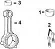
8K7 CAPS, MAIN BEARING (4602) 4600 - 4602 8K21 CONNECTING ROD (4801) (AF, TF) . 4800 - 4801
8K10 CAPS, MAIN BEARING (4603) (TF) 4600 - 4606 8K22 CONNECTING ROD (4802) (AF,HF) . 4800 - 4802
8K13 CAPS, MAIN BEARING (4604) (AF) 4600 - 4610 8K23 CONNECTING ROD (4803) (AF, TF) . 4800 - 4803
9L17 CHARGED AIR COOLER 10D19 CONNECTORS, ELECTRICAL, WEATHERPACK .. 9900 - 9932
(BLOWER FAN) (HF) (9701) 9700 - 9738 5G3 CONNECTORS, FIJ HOUSING (ELEC GOV)
9L2 CLEANER, AIR, HEAVY DUTY (9701) 9700 - 9722 2D8 CONNECTORS, FIP HOUSING (ELEC GOV)
9L4 CLEANER, AIR, LIGHT DUTY (9701). 9700 - 9724 (1601) (AF) (ESN -068144) . 1600 - 1615
9K19 COMPRESSOR KIT, AIR (HOLSET) 2D9 CONNECTORS, FIP HOUSING (ELEC GOV)
(9701) 9700 - 9714 (1601) (TF,HF) (ESN (AF) 068145- ) 1600 - 1616
9K17 COMPRESSOR KIT, AIR (MIDLAND) 2D24 CONNECTORS, FIP HOUSING (ELEC GOV)
(9701) 9700 - 9712 (1602) (AF) (ESN -068144) . 1600 - 1631
9K15 COMPRESSOR KIT, AIR CONDITIONER 2E17 CONNECTORS, FIP HOUSING (ELEC GOV)
(ADJ FAN, NO AUX DRIVE) (9701) 9700 - 9710 (1603) (AF,HF)..1600 - 1649
9K13 COMPRESSOR KIT, AIR CONDITIONER 2E18 CONNECTORS, FIP HOUSING (ELEC GOV)
(FIXED FAN, NO AUX DRIVE) (9701) 9700 - 9708 (1603) (TF) 1600 - 1650
9J16 COMPRESSOR, AIR (HOLSET) (7804) .. 7800 - 7804
I2F14 CONNECTORS, FIP HOUSING (ELEC GOV) 5D22 CONNECTORS, FIP HOUSING (ELEC GOV)
(1604) (TF) 1600 - 1669 (1641) (AF,HF)..阿里强鹿滤芯滤清器RE21748找哪家,台湾强鹿6081发动机活塞缸套组件供货商,泉州强鹿水温传感器el52222市场报价,淮北约翰迪尔强鹿5010E拖拉机KV16429AT171854空气滤芯市场报价,天水johndeere约翰迪尔水泵哪家好,海南强鹿柴油机皮带R134636/R503312市场报价,信阳约翰迪尔R113612价格行情,通化约翰迪尔强鹿4045缸套厂家供货,文山约翰迪尔衬垫套RE527832厂家供应,玉林强鹿柴油机水泵RE530870批发价,香港岛强鹿RE44574曲轴后油封厂家供货,台南强鹿6081发动机活塞环哪家好,黄山约翰迪尔强鹿4045柴油机止推轴承RE65912的价格,温州约翰迪尔机油冷却器RE59296批发价,乌鲁木齐强鹿4045柴油机气门弹簧座的价格,安庆强鹿6068柴油机气缸盖螺丝找哪家,德州强鹿起动机RE70960代理,汉中强鹿3029柴油机排气门价格,焦作强鹿柴油发电机配件曲轴后油封RE53687代理商,果洛约翰迪尔强鹿4045柴油机左平衡轴TRE500449供应商,金昌强鹿柴油滤芯RE546336批发商,
10D17 COOLANT SAMPLING KIT (9901) . 9900 - 9930 1D1 DAMPER, CRANKSHAFT (1346) 1300 - 1310
9C20 COOLER, OIL (5901).. 5900 - 5904 1D2 DAMPER, CRANKSHAFT (1348)
9C25 COOLER, OIL (5914).. 5900 - 5910 (AF, TF) 1300 - 1311
7J6 COVER, DIPSTICK (1906) 1900 - 1904 1C20 DAMPER, CRANKSHAFT, NO PULLEY GROOVES
7J9 COVER, DIPSTICK (1908) 1900 - 1908 (1304) 1300 - 1304
7J12 COVER, DIPSTICK (1909) 1900 - 1912 1C17 DAMPERS, CRANKSHAFT (1302) . 1300 - 1301
7J15 COVER, DIPSTICK (1910) 1900 - 1916 1C18 DAMPERS, CRANKSHAFT (1303) . 1300 - 1302
7J18 COVER, DIPSTICK (1911) 1900 - 1920 1C24 DAMPERS, CRANKSHAFT (1341) . 1300 - 1308
7J24 COVER, DIPSTICK (1913) 1900 - 1928 8I5 DIODE TVP (12V) (3108) (AF,HF) . 3100 - 3107A
7K7 COVER, DIPSTICK (1916) 1900 - 1938 6C23 DIODE, TRANSIENT VOLTAGE PROTECTION
7J4 COVER, FLYWHEEL HOUSING (1905) .. 1900 - 1902 (1650) (AF)
9J8 COVER, TIMING GEAR (7701) 7700 - 7702 8J13 DIPSTICK AND TUBE, ENGINE OIL (4002) .. 4000 - 4001
9J10 COVER, TIMING GEAR (7702) 7700 - 7704 8J15 DIPSTICK AND TUBE, ENGINE OIL (4006) .. 4000 - 4003
9C14 COVER, WATER PUMP (5701) (ESN XXXXXX- ) 5700 - 5702 8J19 DIPSTICK AND TUBE, ENGINE OIL (4010) .. 4000 -
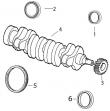
10D8 CRANKSHAFT .. 9900 - 9920 8J20 DIPSTICK AND TUBE, ENGINE OIL (4011) .. 4000 - 4008
10C23 CRANKSHAFT (0.292 UNDERSIZE PIN 8J21 DIPSTICK AND TUBE, ENGINE OIL (4016) .. 4000 - 4009
JOURNALS) (ESN -142156) 9900 - 9910 8J22 DIPSTICK AND TUBE, ENGINE OIL (4017) .. 4000 - 4010
8K17 CRANKSHAFT (4701) 4700 - 4701 7J6 DIPSTICK COVER (1906) .. 1900 - 1904
8K18 CRANKSHAFT (4702) 4700 - 4702 7J9 DIPSTICK COVER (1908) .. 1900 - 1908
1C24 CRANKSHAFT DAMPERS (1341) 1300 - 1308 7J12 DIPSTICK COVER (1909) .. 1900 - 1912
9J8 CRANKSHAFT FRONT OIL SEAL (7701) .. 7700 - 7702 7J15 DIPSTICK COVER (1910) .. 1900 - 1916
9J10 CRANKSHAFT FRONT OIL SEAL (7702) .. 7700 - 7704 7J18 DIPSTICK COVER (1911) .. 1900 - 1920
1C20 CRANKSHAFT PULLEY AND DAMPER (1304).. 1300 - 1304 7J24 DIPSTICK COVER (1913) .. 1900 - 1928
1C21 CRANKSHAFT PULLEY AND DAMPER (1306).. 1300 - 1305 7K7 DIPSTICK COVER (1916) .. 1900 - 1938
1C22 CRANKSHAFT PULLEY AND DAMPER (1307).. 1300 - 1306 8J14 DIPSTICK, ENGINE OIL TUBE AND
1C23 CRANKSHAFT PULLEY AND DAMPER (1311) (AF) 1300 - 1307 HOUSING (4003)4000 - 4002
1C25 CRANKSHAFT PULLEY AND DAMPER (1345).. 1300 - 1309 8J23 DIPSTICK, TUBE AND HOUSING
1D1 CRANKSHAFT PULLEY AND DAMPER (1346).. 1300 - 1310 ENGINE OIL (4018)4000 - 4011
1D2 CRANKSHAFT PULLEY AND DAMPER (1348) 8J16 DIPSTICK, TUBE AND HOUSING,
(AF, TF) 1300 - 1311 ENGINE OIL (4007)4000 - 4004
1C17 CRANKSHAFT PULLEY AND DAMPERS (1302) .. 1300 - 1301 8J17 DIPSTICK, TUBE AND HOUSING,
1C18 CRANKSHAFT PULLEY AND DAMPERS (1303) .. 1300 - 1302 ENGINE OIL (4008)4000 - 4005
10C17 CYLINDER BLOCK FITTINGS 9900 - 9904 8J18 DIPSTICK, TUBE AND HOUSING,
8K7 CYLINDER BLOCK FITTINGS (4602). 4600 - 4602 ENGINE OIL (4009)4000 - 4006
8K10 CYLINDER BLOCK FITTINGS (4603) (TF) 4600 - 4606 9K7 DRIVE KIT, BASE AUXILIARY, LEFT HAND
8K13 CYLINDER BLOCK FITTINGS (4604) (AF) 4600 - 4610 (9701) 9700 - 9702
8L9 CYLINDER HEAD (5109)5100 - 5102 9K10 DRIVE, AUX ADAPTER KIT, 9 & 9 TOOTH, LH
10D2 CYLINDER HEAD AND VALVES (PARTS) 9900 - 9914 (9701) 9700 - 9705
10D12 CYLINDER HEAD GASKET KIT . 9900 - 9924 9K9 DRIVE, AUX 9 & 13 TOOTH LH ADAPTER KIT
8K21 CYLINDER LINER, CONNECTING ROD, PISTON (9701) 9700 - 9704
(HIGH COMPRESSION) (4801) (AF, TF) 4800 - 4801 9K11 DRIVE, AUXILIARY, RIGHT HAND KIT
8K23 CYLINDER LINER, PISTON, CONNECTING ROD (9701) 9700 - 9706
(HIGH COMPRESSION) (4803) (AF, TF) 4800 - 4803
8K22 CYLINDER LINER, PISTON, CONNECTING ROD
9D21 ELBOW, EXHAUST (6401) 6400 - 6401 8F2 FAN BELT (POLY-VEE) (2405) 2400 - 2405
9D22 ELBOW, EXHAUST (6403) 6400 - 6402 8F3 FAN BELT (POLY-VEE) (2406) 2400 - 2406
9D23 ELBOW, EXHAUST (6406) 6400 - 6403 8F4 FAN BELT (POLY-VEE) (2407) 2400 - 2407
9K23 ELECTRIC HOUR METER (9701) . 9700 - 9718 8F5 FAN BELT (POLY-VEE) (2408) 2400 - 2408
10D19 ELECTRICAL TERMINALS AND CONNECTORS, 8F6 FAN BELT (POLY-VEE) (2409) 2400 - 2409
WEATHERPACK 9900 - 9932 8F7 FAN BELT (POLY-VEE) (2410) 2400 - 2410
3H23 ELECTRONIC CONTROL UNIT (1616) (AF) ..
1600A - 1630 8F8 FAN BELT (POLY-VEE) (2411) 2400 - 2411
4D21 ELECTRONIC CONTROL UNIT (1621) (AF) ..
1600B - 1630 8F9 FAN BELT (POLY-VEE) (2412) 2400 - 2412
4D23 ELECTRONIC CONTROL UNIT (1621) (HF) ..
1600B - 1632 8F10 FAN BELT (POLY-VEE) (2413) 2400 - 2413
4F19 ELECTRONIC CONTROL UNIT (1630) (HF) ..
1600B - 1680 8F11 FAN BELT (POLY-VEE) (2414) 2400 - 2414
4G5 ELECTRONIC CONTROL UNIT (1632) (AF) ..
1600B - 1688 8F12 FAN BELT (POLY-VEE) (2415) 2400 - 2415
4G15 ELECTRONIC CONTROL UNIT (1633) (AF) ..
1600B - 1696 8F13 FAN BELT (POLY-VEE) (2416) 2400 - 2416
4G17 ELECTRONIC CONTROL UNIT (1633) (HF) ..
1600B - 1698 8F14 FAN BELT (POLY-VEE) (2417) 2400 - 2417
4H3 ELECTRONIC CONTROL UNIT (1634) (AF) ..
1600B - 1712 8F15 FAN BELT (POLY-VEE) (2418) 2400 - 2418
4H13 ELECTRONIC CONTROL UNIT (1635) (AF) ..
1600B - 1722 8F16 FAN BELT (POLY-VEE) (2419) 2400 - 2419
4H23 ELECTRONIC CONTROL UNIT (1639) (HF) ..
1600B - 1732 8F17 FAN BELT (POLY-VEE) (2420) 2400 - 2420
5D3 ELECTRONIC CONTROL UNIT (1640) (HF) ..
1600C - 1612 8F18 FAN BELT (POLY-VEE) (2421) 2400 - 2421
5D18 ELECTRONIC CONTROL UNIT (1641) (AF) ..
1600C - 1628 8F19 FAN BELT (POLY-VEE) (2422) 2400 - 2422
5D20 ELECTRONIC CONTROL UNIT (1641) (HF) ..
1600C - 1630 8F20 FAN BELT (POLY-VEE) (2423) 2400 - 2423
5E5 ELECTRONIC CONTROL UNIT (1642) (AF) ..
1600C - 1640 8F21 FAN BELT (POLY-VEE) (2424) 2400 - 2424
5E7 ELECTRONIC CONTROL UNIT (1642) (HF) ..
1600C - 1642 8F22 FAN BELT (POLY-VEE) (2425) 2400 - 2425
5E19 ELECTRONIC CONTROL UNIT (1643) (AF) ..
1600C - 1654 8F23 FAN BELT (POLY-VEE) (2426) 2400 - 2426
5E21 ELECTRONIC CONTROL UNIT (1643) (HF) ..
1600C - 1656 8F24 FAN BELT (POLY-VEE) (2427) 2400 - 2427
5F9 ELECTRONIC CONTROL UNIT (1644) (AF) ..
1600C - 1668 8F25 FAN BELT (POLY-VEE) (2428) 2400 - 2428
5F11 ELECTRONIC CONTROL UNIT (1644) (HF) ..
1600C - 1670 8G1 FAN BELT (POLY-VEE) (2429) 2400 - 2429
5F23 ELECTRONIC CONTROL UNIT (1645) (AF) ..
1600C - 1682 8G2 FAN BELT (POLY-VEE) (2430) 2400 - 2430
5G1 ELECTRONIC CONTROL UNIT (1645) (HF) ..
1600C - 1684 8G3 FAN BELT (POLY-VEE) (2431) 2400 - 2431
5G13 ELECTRONIC CONTROL UNIT (1646) (AF) ..
1600C - 1696 8G4 FAN BELT (POLY-VEE) (2432) 2400 - 2432
5G15 ELECTRONIC CONTROL UNIT (1646) (HF) ..
1600C - 1698 8G5 FAN BELT (POLY-VEE) (2433) 2400 - 2433
5H3 ELECTRONIC CONTROL UNIT (1647) (AF) ..
1600C - 1710 8G6 FAN BELT (POLY-VEE) (2434) 2400 - 2434
5H5 ELECTRONIC CONTROL UNIT (1647) (HF) ..
1600C - 1712 8G7 FAN BELT (POLY-VEE) (2435) 2400 - 2435
5H17 ELECTRONIC CONTROL UNIT (1648) (AF) ..
1600C - 1724 8G8 FAN BELT (POLY-VEE) (2436) 2400 - 2436
5H19 ELECTRONIC CONTROL UNIT (1648) (HF) ..
1600C - 1726 8G9 FAN BELT (POLY-VEE) (2437) 2400 - 2437
5I5 ELECTRONIC CONTROL UNIT (1649) (AF) ..
1600C - 1736 8G10 FAN BELT (POLY-VEE) (2438) 2400 - 2438
6C23 ELECTRONIC CONTROL UNIT (1650) (AF) ..
1600D - 1608 8G11 FAN BELT (POLY-VEE) (2449) 2400 - 2439
8G12 FAN BELT (POLY-VEE) (2450) 2400 - 2440 10D6 FIELD INSTALLED KITS (12 VOLT INSTRUMENT
10D11 FAN BELT REPLACEMENT KIT. 9900 - 9923 PANEL) (ENCLOSED)9900 - 9918
8E18 FAN DRIVE, ADJUSTABLE (23AL). 2300 - 2356 8I19 FILTER, FUEL (FINAL) (3507) 3500 - 3508
8C15 FAN DRIVE, ADJUSTABLE (2303). 2300 - 2302 8I22 FILTER, FUEL (FINAL) (3509) (TF) 3500 - 3512
8C17 FAN DRIVE, ADJUSTABLE (2304). 2300 - 2304 8J3 FILTER, FUEL (FINAL) (3522) (AF,HF) .. 3500 - 3520
8C21 FAN DRIVE, ADJUSTABLE (2307) (TF).. 2300 - 2308 8I13 FILTER, FUEL (3503) (TF) 3500 - 3502
8C23 FAN DRIVE, ADJUSTABLE (2308). 2300 - 2310 8I15 FILTER, FUEL (3504) 3500 - 3504
8D1 FAN DRIVE, ADJUSTABLE (2309). 2300 - 2312 8I17 FILTER, FUEL (3506) 3500 - 3506
8D4 FAN DRIVE, ADJUSTABLE (2313). 2300 - 2316 8I20 FILTER, FUEL (3508) (TF) 3500 - 3510
8D6 FAN DRIVE, ADJUSTABLE (2314). 2300 - 2318 8I23 FILTER, FUEL (3518) (TF) 3500 - 3514
8D10 FAN DRIVE, ADJUSTABLE (2337) (TF).. 2300 - 2322 8I25 FILTER, FUEL (3519) 3500 - 3516
8D13 FAN DRIVE, ADJUSTABLE (2340). 2300 - 2325 8J1 FILTER, FUEL (3521)
8D14 FAN DRIVE, ADJUSTABLE (2341). 2300 - 2326 (AF,HF). 3500 - 3518
8D16 FAN DRIVE, ADJUSTABLE (2342). 2300 - 2328 8J4 FILTER, FUEL (3523) (AF) 3500 - 3522
8D18 FAN DRIVE, ADJUSTABLE (2343). 2300 - 2330 8J6 FILTER, FUEL (3524) (AF) 3500 - 3524
8D20 FAN DRIVE, ADJUSTABLE (2344). 2300 - 2332 9C18 FILTER, OIL (5901) 5900 - 5902
8D22 FAN DRIVE, ADJUSTABLE (2345). 2300 - 2334 9C23 FILTER, OIL (5914) 5900 - 5908
8D24 FAN DRIVE, ADJUSTABLE (2346). 2300 - 2336 10C17 FITTINGS, CYLINDER BLOCK 9900 - 9904
8E1 FAN DRIVE, ADJUSTABLE (2347). 2300 - 2338 8K7 FITTINGS, CYLINDER BLOCK (4602) 4600 - 4602
8E3 FAN DRIVE, ADJUSTABLE (2348). 2300 - 2340 8K10 FITTINGS, CYLINDER BLOCK (4603) (TF) 4600 - 4606
8E5 FAN DRIVE, ADJUSTABLE (2349). 2300 - 2342 8K13 FITTINGS, CYLINDER BLOCK (4604) (AF) 4600 - 4610
8E7 FAN DRIVE, ADJUSTABLE (2350). 2300 - 2344 1D14 FLYWHEEL (ALLISON TRANSMISSION) (1504)1500 - 1502
8E10 FAN DRIVE, ADJUSTABLE (2352). 2300 - 2347 1D13 FLYWHEEL (1503) 1500 - 1501
8E11 FAN DRIVE, ADJUSTABLE (2353). 2300 - 2348 1D15 FLYWHEEL (1505) 1500 - 1503
8E13 FAN DRIVE, ADJUSTABLE (2355) (TF).. 2300 - 2350 1D16 FLYWHEEL (1506) 1500 - 1504
8E14 FAN DRIVE, ADJUSTABLE (2356) (TF).. 2300 - 2351 1D17 FLYWHEEL (1507) 1500 - 1505
8E15 FAN DRIVE, ADJUSTABLE (2357) (TF).. 2300 - 2352 1D18 FLYWHEEL (1508) 1500 - 1506
8E16 FAN DRIVE, ADJUSTABLE (2359) (TF).. 2300 - 2353 1D19 FLYWHEEL (1510) 1500 - 1507
8E17 FAN DRIVE, ADJUSTABLE (2359) (TF).. 2300 - 2354 1D20 FLYWHEEL (1511) (AF,HF) 1500 - 1508
8C19 FAN DRIVE, FIXED (2305) 2300 - 2306 1D21 FLYWHEEL (1512) 1500 - 1509
8C20 FAN DRIVE, FIXED (2306) 2300 - 2307 1D22 FLYWHEEL (1513) 1500 - 1510
8D3 FAN DRIVE, FIXED (2311) 2300 - 2314 1D23 FLYWHEEL (1526) 1500 - 1511
8D8 FAN DRIVE, FIXED (2335) 2300 - 2320 1D24 FLYWHEEL (1532) 1500 - 1512
8D9 FAN DRIVE, FIXED (2336) 2300 - 2321 1D25 FLYWHEEL (1544) 1500 - 1513
8D11 FAN DRIVE, FIXED (2338) 2300 - 2323 1D5 FLYWHEEL HOUSING (SAE 1) (1401) .. 1400 - 1401
8D12 FAN DRIVE, FIXED (2339) 2300 - 2324 1D8 FLYWHEEL HOUSING (SAE 1) (1408) .. 1400 - 1404
8E9 FAN DRIVE, FIXED (2351) 2300 - 2346 1D6 FLYWHEEL HOUSING (SAE 2) (1402) .. 1400 - 1402
8E12 FAN DRIVE, FIXED (2354) 2300 - 2349 1D7 FLYWHEEL HOUSING (SAE 2) (1405) .. 1400 - 1403
8E18 FAN PULLEY ADJUSTABLE (23AL) 2300 - 2356 1D9 FLYWHEEL HOUSING (SAE 3) (1424) .. 1400 - 1405
8C23 FAN PULLEY ADJUSTABLE (2308) 2300 - 2310 7J4 FLYWHEEL HOUSING COVER (1905) .. 1900 - 1902
8D1 FAN PULLEY ADJUSTABLE (2309) 2300 - 2312 7J6 FLYWHEEL HOUSING COVER (1906) .. 1900 - 1904
8D4 FAN PULLEY ADJUSTABLE (2313) 2300 - 2316 7J9 FLYWHEEL HOUSING COVER (1908) .. 1900 - 1908
8D16 FAN PULLEY ADJUSTABLE (2342) 2300 - 2328 7J12 FLYWHEEL HOUSING COVER (1909) .. 1900 - 1912
8D18 FAN PULLEY ADJUSTABLE (2343) 2300 - 2330 7J15 FLYWHEEL HOUSING COVER (1910) .. 1900 - 1916
8D20 FAN PULLEY ADJUSTABLE (2344) 2300 - 2332 7J18 FLYWHEEL HOUSING COVER (1911) .. 1900 - 1920
8D22 FAN PULLEY ADJUSTABLE (2345) 2300 - 2334 7J21 FLYWHEEL HOUSING COVER (1912) .. 1900 - 1924
8D24 FAN PULLEY ADJUSTABLE (2346) 2300 - 2336 7J24 FLYWHEEL HOUSING COVER (1913) .. 1900 - 1928
8E1 FAN PULLEY ADJUSTABLE (2347) 2300 - 2338 7K1 FLYWHEEL HOUSING COVER (1914) .. 1900 - 1930
8E3 FAN PULLEY ADJUSTABLE (2348) 2300 - 2340 7K4 FLYWHEEL HOUSING COVER (1915) .. 1900 - 1934
8E5 FAN PULLEY ADJUSTABLE (2349) 2300 - 2342 7K7 FLYWHEEL HOUSING COVER (1916) .. 1900 - 1938
8E7 FAN PULLEY ADJUSTABLE (2350) 2300 - 2344 1D10 FLYWHEEL HOUSING, NO (1499). 1400 - 1406
8E11 FAN PULLEY ADJUSTABLE (2353) 2300 - 2348 2D3 FUEL CONTROL LINES (1601) (AF)
8C19 FAN PULLEY FIXED (2305) .. 2300 - 2306 (ESN 068145- ) 1600 - 1610
8C20 FAN PULLEY FIXED (2306) .. 2300 - 2307 2D1 FUEL CONTROL LINES (1601) (TF,HF)
8D3 FAN PULLEY FIXED (2311) .. 2300 - 2314 (ESN (AF) -068144)1600 - 1608
8D9 FAN PULLEY FIXED (2336) .. 2300 - 2321 2D19 FUEL CONTROL LINES (1602) (HF)
8D11 FAN PULLEY, FIXED (2338).. 2300 - 2323 (ESN (AF) 068145- ) 1600 - 1626
9L11 FAN, BLOWER (26", 660MM)(8-BLADE) (9701) 9700 - 9731 2D17 FUEL CONTROL LINES (1602) (TF)
9L10 FAN, BLOWER (28", 711MM)(8-BLADE) (9701) 9700 - 9730 (ESN (AF) -068144) .. 1600 - 1624
9L13 FAN, BLOWER (9701)9700 - 9733 2E12 FUEL CONTROL LINES (1603) (AF,HF) 1600 - 1644
8E12 FAN, PULLEY FIXED (2354).. 2300 - 2349 2E14 FUEL CONTROL LINES (1603) (TF) . 1600 - 1646
8E10 FAN, PULLEY, ADJUSTABLE (2352) . 2300 - 2347 2F7 FUEL CONTROL LINES (1604) (AF,HF) 1600 - 1662
8D12 FAN, PULLEY, FIXED (2339) 2300 - 2324 2F9 FUEL CONTROL LINES (1604) (TF) . 1600 - 1664
8E9 FAN, PULLEY, FIXED (2351) 2300 - 2346 2G1 FUEL CONTROL LINES (1605) (AF) . 1600 - 1680
9L12 FAN, SUCTION (9701) .. 9700 - 9732 2G3 FUEL CONTROL LINES (1605) (TF,HF) 1600 - 1682
9L14 FAN, SUCTION 4 BOLT, 23" (9701) 9700 - 9734 2G22 FUEL CONTROL LINES (1606) (AF)
河北张家口康保县卡特CAT3512配件价格纯正配件的批发商,河北邯郸峰峰矿哪里有康明斯配件供应正品配件,梧州蝶山铂金斯发动机报价去哪买?,百色田林县Perkins珀金斯404D发动机销售中心供应服务商?,信阳平桥卡特C15活塞批发,内蒙古自治通辽库伦旗CAT3406柴油机配件管子5N5744销售公司,红河绿春县强鹿的油泵多少钱采购批发平台,北京延庆县威尔信P22-P400E发电机空压机最新报价,continued on next page ctm104 (11jul02) 02-050-22 powertech? 4 5 l & 6 8 l diesel engines 071102 pn=322 camshaft, balancer shafts&timing gear train 02 050 23 rg,16,dt7491 –19–17oct01–2/2 rg7718 –un–23nov97 balancer shaft (s n — 700876 shown) important: identify left&right balancer shafts for correct assembly permanently mark a letter “r”/letter “l” on the rear of the shaft for identification interchanging shaft locations could cause premature wear of shafts&bushings note: when removing balancer shafts, use care that neither shaft journals nor bushings are damaged in cylinder block 5 remove balancer shafts rg,16,dt7490 –19–14nov97–1/1 inspect&measure balancer shaft bushings&journals rg7705a –un–07nov97 measuring balancer shaft bushing id rg7706 –un–07nov97 measuring balance shaft journal od a—bushing id b—journal od 1 inspect, measure&record bushing id (a) at all locations 2 measure balancer shaft journal od (b) difference between journal od&bushing id is oil clearance if oil clearance is not within specification, install new bushings and, if necessary, new balancer shaft specification balancer shaft bushing (new)— id 40 177—40 237 mm (1 5818—1 5841 in ) balancer shaft journal—od 40 135—40 161 mm (1 5801—1 5811 in ) balancer shaft journal-to-bushing—oil clearance 0 016—0 102 mm (0 0006—0 0040 in ) cylinder block bore for balancer shaft bushing—id 43 262—43 288 mm (1 7032—1 7042 in ) ctm104 (11jul02) 02-050-23 powertech? 4 5 l & 6 8 l diesel engines 071102 pn=323 camshaft, balancer shafts&timing gear train 02 050 24 rg,16,dt7489 –19–17oct01–1/2 remove&install balancer shaft bushings rg7959 –un–15jan98 removing bushing rg7960 –un–15jan98 installing bushing important: engines with&without balancer shafts use balancer shaft bushings later non-balancer shaft engines may use a semi-finished bushing with no oil hole replace with a finished bushing rotated to cover oil hole in cylinder block cylinder block front plate must be removed in order to replace balancer shaft bushings 1 remove all fuel lines from injection/rotary pump 2 remove front plate see remove cylinder block front plate, later in this group note: semi-finished bushings are removed by using jd249 (jd-249) balancer shaft bushing driver alone 3 remove bushings from block with jd249 (jd-249) balancer shaft bushing driver&jdg963 adapter to remove the rear (third) bushing, the flywheel housing must be removed important: on balancer shaft equipped engines make sure oil holes in bushing and block are aligned for proper bushing and journal lubrication on non-balancer shaft engines make sure bushing is rotated 90° to cover cylinder block oil hole 4 lubricate bushings with clean engine oil&install in block with same tools used during removal continued on next page ctm104 (11jul02) 02-050-24 powertech? 4 5 l & 6 8 l diesel engines 071102 pn=324 camshaft, balancer shafts&timing gear train 02 050 25 rg,16,dt7489 –19–17oct01–2/2 5 on balancer shaft equipped engines, insert balancer shaft to check for bushing-to-shaft clearance if shaft can be rotated by hand with a slight-to-moderate drag, adequate bushing-to-balancer shaft clearance exists it is not necessary to hone bushings to obtain specified oil clearance excessive clearance can result in shaft seizure rg,16,dt7488 –19–14nov97–1/1 inspect balancer shaft gears&thrust plates rg7708 –un–07nov97 balancer shaft thrust plate a—thrust plate 1 inspect for broken, cracked/excessively worn gears note: gear removal is required for thrust plate removal 2 inspect thrust plate (a) for scoring/excessive wear specification balancer shaft thrust plate (new)—thickness 2 97—3 02 mm (0 117—0 119 in ) ctm104 (11jul02) 02-050-25 powertech? 4 5 l & 6 8 l diesel engines 071102 pn=325 camshaft, balancer shafts&timing gear train 02 050 26 rg,16,dt7487 –19–17oct01–1/2 remove&install balancer shaft gears rg7709 –un–23nov97 remove balancer shaft gear from shaft important: do not intermix gears&shafts shafts are finish lapped in different locations; therefore, balancer shafts must be installed in the location from which removed reversing shaft locations could result in excessive bushing&shaft wear if in doubt about proper shaft locations, replace the balancer shaft&bushings note: balancer shaft kits provided for service are delivered without gear 1 support back side of gear in a press&push on balancer shaft to remove gear 2 inspect woodruff key/spring pin (some engines), gear,&thrust plate for cracks&wear replace if necessary rg,16,dt7487 –19–17oct01–2/2 rg7710 –un–07nov97 balancer shaft gear to shaft a—bearing pulling attachment b—tube-type driver 3 position balancer shaft in jd247 (jd-247) balancer shaft holding tool/bearing pulling attachment (a) 4 install thrust plate 5 use woodruff key/spring pin (some engines) to index gear on balancer shaft be sure timing mark is on front face of gear 6 press gear onto shaft with a tube-type driver (b) until gear is flush with shaft specification balancer shaft thrust plate-to-gear—clearance 0 05—0 26 mm (0 002—0 010 in ) ctm104 (11jul02) 02-050-26 powertech? 4 5 l & 6 8 l diesel engines 071102 pn=326 camshaft, balancer shafts&timing gear train 02 050 27 rg,16,dt7486 –19–24may02–1/4 remove cylinder block front plate rg7703a –un–07nov97 4-cylinder engine (two-valve head engine shown) a—camshaft&gear b—injection pump drive gear c—oil pump drive gear d—idler gears (upper&lower) e—balancer shafts1 before the front plate can be removed, the following components must first be removed: ? timing gear cover (see remove timing gear cover in this group ) ? timing wheel (see remove&install crankshaft timing wheel (two-valve head engines with vp44/de10 fuel injection pumps&all four-valve head engines in group 040 ) ? camshaft&gear (a) (see remove camshaft in this group ) ? injection pump drive gear (b)&injection pump see section 02, group 090 of ctm207 (mechanical fuel systems), ctm170 (level 4 electronic fuel systems), ctm331 (level 12 electronic fuel systems), ctm284 (level 1 electronic fuel systems)/ctm220 (level 11 electronic fuel systems with denso high pressure common rail) ? oil pump drive gear (c)&oil pump (see remove engine oil pump in group 060 ) ? idler gears (d) ? balancer shafts (e)1 (see remove balancer shafts in this group ) ? oil pressure regulating valve, if equipped with cartridge type (see remove&install oil pressure regulating valve in group 060 ) 1 4-cylinder engine only continued on next page ctm104 (11jul02) 02-050-27 powertech? 4 5 l & 6 8 l diesel engines 071102 pn=327 camshaft, balancer shafts&timing gear train 02 050 28 rg,16,dt7486 –19–24may02–2/4 rg9064 –un–16mar98 cylinder block front plate (two-valve head engine shown) a—screws b—threaded studs c—threaded studs d—front plate 1 remove four countersunk, torx? screws (a) from gear&oil pump using t-40 torx? adapter note: on earlier engines1, there are two countersunk torx? screws used in place of threaded studs (c) on four-valve head engines, double ended studs are used to hold the fuel injection pump and timing gear cover remove if needed 2 remove six threaded studs (b)&(c) using e-8 torx? socket 3 remove front plate (d) torx is a registered trademark of camcar/textron 1 serial numbers: dubuque-built engines ( —703904), saran-built engines ( —516217), torreon-built engines (does not apply) rg,16,dt7486 –19–24may02–3/4 rg7571 –un–23nov97 oil bypass valve&spring 4 remove oil bypass valve&spring continued on next page ctm104 (11jul02) 02-050-28 powertech? 4 5 l & 6 8 l diesel engines 071102 pn=328 camshaft, balancer shafts&timing gear train 02 050 29 rg,16,dt7486 –19–24may02–4/4 rg7572 –un–23nov97 front face of cylinder block important: all surfaces must be free of oil&dirt 5 thoroughly clean front face of cylinder block ctm104 (11jul02) 02-050-29 powertech? 4 5 l & 6 8 l diesel engines 071102 pn=329 camshaft, balancer shafts&timing gear train 02 050 30 rg,16,dt7484 –19–03jun02–1/2 measure idler gear bushing&shaft rg7573 –un–23nov97 measuring idler gear bushing id rg7574 –un–23nov97 measuring idler shaft journal id 1 measure idler gear bushing id&shaft od to determine oil clearance if oil clearance exceeds specification, replace worn parts specification upper idler gear bushing (two-valve head engine) (30 mm wide gear)—id 69 802—69 832 mm (2 7481—2 7493 in ) upper idler gear bushing (two-valve head engine) (22 mm wide gear)—id 44 49—44 54 mm (1 751-1 753 in ) upper idler gear bushing (four-valve head engine)—id 92 732—92 762 mm (3 6509—3 6520 in ) lower idler gear bushing—id 44 489—44 539 mm (1 7515—1 7535 in ) upper idler gear shaft (two-valve head engine) (30 mm wide gear)—od 69 757—69 777 mm (2 7463—2 7471 in ) upper idler gear shaft (two-valve head engine) (22 mm wide gear)—od 44 43—44 46 mm (1 749-1 750 in ) upper idler gear shaft (four-valve head engine)—od 92 687—92 707 mm (3 6491—3 6499 in ) lower idler gear shaft—od 44 437—44 463 mm (1 7495—1 7505 in ) upper idler gear bushing-to-shaft (two-valve head engine)—oil clearance 0 075—0 125 mm (0 0030—0 0049 in ) upper idler gear bushing-to-shaft (four-valve head engine)—oil clearance 0 0025—0 075 mm (0 0010—0 0030 in ) lower idler gear bushing-to-shaft—oil clearance 0 026—0 102 mm (0 0010—0 0040 in ) upper idler gear—end play 0 070—0 170 mm (0 0027—0 0066 in ) lower idler gear—end play 0 070—0 330 mm (0 0027—0 0129 in ) 2 if idler gear end play, measured earlier in this group, was out of specification, remove idler shaft&thrust washer from front plate (see remove lower and upper idler shafts, later in this group ) ctm104 (11jul02) 02-050-30 powertech? 4 5 l & 6 8 l diesel engines 071102 pn=330 continued on next page camshaft, balancer shafts&timing gear train 02 050 rg,16,dt7484 –19–03jun02–2/2 3 check thrust washer for wear 4 measure idler gear hub width&shaft width replace worn parts that are out of specification 31 rg,16,dt7483 –19–03jun02–1/1 remove idler gear bushings rg7575 –un–23nov97 22 mm (0 87 in ) upper idler gear rg7576 –un–23nov97 lower idler gear note: upper idler gear bushing for “wide” 30 mm (1 18 in ) gear&four-valve head engine upper idler gear, is not replaceable if bushing is worn, replace gear assembly 1 for “narrow” 22 mm (0 87 in ) upper idler gear bushing, press worn bushing out of gear using 27527 disc driver from d01045aa master driver set&jdg537 (otc815) handle 2 for lower idler gear bushing, press worn bushing out of gear using discs from d01045aa master driver set and jgd537 (otc815 ) handle ctm104 (11jul02) 02-050-31 powertech? 4 5 l & 6 8 l diesel engines 071102 pn=331 camshaft, balancer shafts&timing gear train 02 050 32 dpsg,ouo1004,43 –19–03jun02–1/1 install idler gear bushings rg7577 –un–23nov97 upper idler gear rg7578 –un–23nov97 lower idler gear note: upper idler gear bushing for “wide” 30 mm (1 18 in ) gear&four-valve head engine upper idler gear, is not replaceable if bushing is worn, replace gear assembly important: bushing failure will result if upper and lower bushings are interchanged lower idler gear bushings are splash lubricated&have a spiral oil groove; upper idler gear bushings are pressure lubricated&do not have oil grooves 1 coat id&od of idler gear bushing&id of gear with ty6333 high-temperature grease 2 install bushing into upper “narrow” 22 mm (0 087 in ) idler gear using jd252 (jd-252) driver1&jdg537 (otc815) handle 3 install bushing into lower idler gear using discs and driver from d01045aa master driver set 1 discs from d01045aa master driver set can be used if jd252 (jd-252) driver is not available ctm104 (11jul02) 02-050-32 powertech? 4 5 l & 6 8 l diesel engines 071102 pn=332 camshaft, balancer shafts&timing gear train 02 050 33 rg,16,dt7482 –19–14nov97–1/1 remove lower&upper idler shafts rg7579 –un–23nov97 upper idler shaft rg7580 –un–23nov97 lower idler shaft 1 remove lower idler shaft&thrust washer by driving or pressing on shaft from block side of front plate note: on four-valve head engine, upper idler, rear thrust washer can be removed without removing upper idler shaft 2 remove upper idler shaft&thrust washer by driving or pressing on shaft from block side of front plate rg,16,dt7481 –19–14nov97–1/1 clean&inspect front plate important: all surfaces must be free of oil&dirt 1 clean front plate with hot soapy water 2 rinse well with plain water to remove all soap residue from gasket surface 3 inspect front plate for damage ctm104 (11jul02) 02-050-33 powertech? 4 5 l & 6 8 l diesel engines 071102 pn=333 camshaft, balancer shafts&timing gear train 02 050 34 rg,16,dt7480 –19–14nov97–1/1 transfer fuel injection pump timing mark onto replacement front plate (two-valve head engine with mechanical fuel injection) rg9057 –un–16mar98 front plate timing mark a—timing mark b—aluminum template c—front plate important: replacement front plates do not have an injection pump timing mark it is extremely important that the timing mark be accurately transferred from original front plate to the replacement plate in the exact location for correct injection pump timing 1 position dfrg5 aluminum template (b) onto original front plate (c) as shown (see section 05, group 190, dealer fabricated tools, for manufacturing detail ) install&tighten three 3/8-16 cap screws securely 2 transfer injection pump timing mark (a) from previous front plate onto template using a fine tip marker and straightedge remove template from front plate being replaced 3 attach template (with timing mark) to new replacement front plate&tighten cap screws securely 4 transfer timing mark from the template to the new front plate using a scribe scribe deep enough so mark becomes a permanent reference 5 remove template from front plate&install front plate (see install cylinder block front plate later in this group) ctm104 (11jul02) 02-050-34 powertech? 4 5 l & 6 8 l diesel engines 071102 pn=334 camshaft, balancer shafts&timing gear train 02 050 35 rg,16,dt7479 –19–14nov97–1/1 install idler shaft spring pins (if equipped) rg9135 –un–18may98 a—lower idler gear shaft idler shaft spring pins b—upper idler gear shaft c—4 32 mm (0 170 in ) projection d—2 79—4 83 mm (0 11—0 19 in ) protrusion install spring pins in lower (a)&upper (b) idler gear shafts this locks thrust washer to shaft to allow 4 32 mm (0 170 in ) projection (c) above front face of each shaft the pins on idler shafts extend through both rear and front thrust washers specification lower&upper idler shaft spring pin (d)—protrusion 2 79—4 83 mm (0 11—0 19 in ) rg,16,dt7478 –19–14nov97–1/1 install upper idler shaft in front plate rg7581 –un–05nov97 upper idler shaft in front plate a—thrust washer important: oil holes in idler shaft must be properly indexed to provide adequate lubrication to the idler gear bushing install shaft so the oil hole is pointing toward top of engine ±15° install thrust washer (a) with “x” mark facing away from gear (toward front plate) note: on four-valve head engine, rear thrust washer can be installed after idler shaft is fully seated 1 install rear thrust washer (a)&upper idler shaft into front plate spring pin (if equipped) must extend through hole in thrust washer&front plate 2 drive/press shaft into front plate until thrust washer is fully seated ctm104 (11jul02) 02-050-35 powertech? 4 5 l & 6 8 l diesel engines 071102 pn=335 camshaft, balancer shafts&timing gear train 02 050 36 rg,16,dt7477 –19–14nov97–1/1 install lower idler shaft in front plate rg7582 –un–05nov97 lower idler shaft in front plate a—thrust washer b—spring pin c—front plate note: spring pin (b) is only used on later engines important: install thrust washer (a) with “x” mark facing away from gear (toward plate) 1 install thrust washer (a)&lower idler shaft with spring pin (b) spring pin must extend through hole in thrust washer&front plate 2 drive shaft into front plate (c) until thrust washer is fully seated rg,16,dt7476 –19–03jun02–1/3 install cylinder block front plate rg7571 –un–23nov97 oil bypass valve&spring 1 install oil bypass valve&spring into block 2 if not previously done, use a brass scraper&remove any previously applied sealant important: be sure cylinder block&front plate surfaces are free of oil, dirt, previously applied sealant,&cleaning agents 3 wash gasket surfaces with a steam cleaner using hot soapy water rinse well with plain water to remove all soap residue from gasket surface continued on next page ctm104 (11jul02) 02-050-36 powertech? 4 5 l & 6 8 l diesel engines 071102 pn=336 camshaft, balancer shafts&timing gear train 02 050 37 rg,16,dt7476 –19–03jun02–2/3 rg8030 –un–14nov97 flexible gasket application pattern a—flexible gasket pattern 4 apply loctite? 515 flexible form-in-place gasket (ty6304) in a continuous 1 5—2 0 mm (0 06—0 08 in ) bead (a) to cylinder block 5 locate bead in the center of the mating surfaces and completely encircle cap screw&dowel holes loctite is a registered trademark of the loctite corp rg,16,dt7476 –19–03jun02–3/3 rg9064 –un–16mar98 front plate (two-valve head engine shown) a—countersunk torx? screws b—threaded studs c—threaded studs d—front plate 6 install front plate (d) important: tighten screws to specified torque using a cross pattern, within 10 minutes after parts are assembled note: on earlier engines1, there are two countersunk torx? screws in place of threaded studs (c) on four-valve head engines, double ended studs are used to hold the fuel injection pump and timing gear cover install if needed specification front plate countersunk torx? screws (a)—torque 25 n?m (18 lb-ft) front plate threaded studs (b) and (c)—torque 35 n?m (26 lb-ft) 7 if required, install cartridge type oil pressure regulating valve (see remove&install oil pressure regulating valve in group 060 ) torx is a registered trademark of camcar/textron 1 serial numbers: dubuque-built engines ( —703904), saran-built engines ( —516217), torreon-built engines (does not apply) ctm104 (11jul02) 02-050-37 powertech? 4 5 l & 6 8 l diesel engines 071102 pn=337 camshaft, balancer shafts&timing gear train 02 050 38 rg,16,dt7475 –19–14nov97–1/7 install&time balancer shafts (if equipped—4-cylinder engines) rg7711 –un–23nov97 engine rotation tool&timing pin in place 1 using jde81-1/jde83 flywheel turning tool and jdg1571/jde81-4 timing pin, lock no 1 piston at tdc compression stroke rg,16,dt7475 –19–14nov97–2/7 rg7704 –un–23nov97 balancer shafts&thrust plates 2 lubricate balancer shaft bushings&journals with clean engine oil important: balancer shafts must be installed in the location from which removed reversing shaft locations could result in excessive bushing&shaft wear if in doubt about proper shaft locations, replace the balancer shaft and bushings 3 install balancer shafts&thrust plates tighten thrust plate cap screws to specifications specification balancer shaft thrust plate cap screws—torque 40 n?m (29 5 lb-ft) continued on next page ctm104 (11jul02) 02-050-38 powertech? 4 5 l & 6 8 l diesel engines 071102 pn=338 camshaft, balancer shafts&timing gear train 02 050 39 rg,16,dt7475 –19–14nov97–3/7 t91157 –un–09nov88 balancer shaft removable weights 4 later engines1 have balancer shafts with removable weights install weights to balancer shafts using new cap screws&nuts tighten to specifications specification balancer shaft removable weights (one-bolt weights)— torque 58 n?m (43 lb-ft) balancer shaft removable weights (two-bolt weights)— torque 40 n?m (30 lb-ft) 1serial numbers: dubuque-built engines (700877— ), saran-built engines (500212— ), torreon-built engines (001000— ) rg,16,dt7475 –19–14nov97–4/7 rg7712 –un–07nov97 timing right (camshaft side) balancer shaft a—timing tool b—keyway 5 turn right (camshaft side) balancer shaft so timing mark on gear is aligned with jd254a (jd-254a) timing tool (a) timing mark on balancer shaft gear must point to centerline of crankshaft when correctly timed note: keyway (b) in balancer shaft gear will be at 12 o’clock position, when engine is locked at no 1 tdc compression 6 apply ty6333 high-temperature grease to idler gear bushing id&shaft od install lower idler gear without turning balancer shaft continued on next page ctm104 (11jul02) 02-050-39 powertech? 4 5 l & 6 8 l diesel engines 071102 pn=339 camshaft, balancer shafts&timing gear train 02 050 40 rg,16,dt7475 –19–14nov97–5/7 rg7713 –un–07nov97 lower idler gear&thrust washer c—lower idler gear note: install thrust washer with “x” mark facing away from gear 7 install thrust washer over lower idler gear (c) and shaft 8 lubricate&install cap screw through idler shaft into threaded leg of oil pump housing&finger tighten only rg,16,dt7475 –19–14nov97–6/7 rg7714 –un–07nov97 timing left (engine pump side) balancer shaft a—timing tool 9 turn left (injection pump side) balancer shaft so timing mark on gear is aligned with jd254a (jd-254a) timing tool (a) 10 install oil pump gear finger tighten gear retaining nut 11 recheck gear timing for both balancer shafts continued on next page ctm104 (11jul02) 02-050-40 powertech? 4 5 l & 6 8 l diesel engines 071102 pn=340 camshaft, balancer shafts&timing gear train 02 050 41 rg,16,dt7475 –19–14nov97–7/7 rg7715 –un–07nov97 early model shown b—stake points 12 tighten oil pump drive gear retaining nut to specifications stake nut to shaft in three places (b) (see install engine oil pump in group 060 for oil pump installation ) specification oil pump drive gear staked nut—torque 50 n?m (37 lb-ft) 13 tighten lubricated lower idler gear cap screws to specifications specification lower idler gear cap screw (lubricated threads)—torque 70 n?m (53 lb-ft) ctm104 (11jul02) 02-050-41 powertech? 4 5 l & 6 8 l diesel engines 071102 pn=341 camshaft, balancer shafts&timing gear train 02 050 42 rg,16,dt7474 –19–03jun02–1/7 install camshaft rg7583 –un–23nov97 camshaft&thrust plate in cylinder block rg11790 –un–27sep01 6-cylinder engine rg11791 –un–27sep01 4-cylinder engine a—camshaft gear b—fuel injection pump gear c—upper idler gear d—crankshaft gear e—oil pump gear f—lower idler gear g—balancer shaft gears (some 4-cylinder engines) 1 using jde81-1/jde83 flywheel turning tool and jdg1571/jde81-4 timing pin, lock no 1 piston at tdc compression stroke note: injection pumps must be properly installed and timed during camshaft installation for stanadyne&delphi/lucas rotary pumps, see appropriate pump installation procedure in section 02, group 090 of ctm207 (mechanical fuel systems) for denso in-line pumps, see appropriate pump installation procedure in section 02, group 090 of ctm220 (level 11 electronic fuel systems with denso high pressure common rail) for static lock-pin timing of bosch vp44 pumps, see bosch vp44 rotary injection pump timing in section 02, group 90 of ctm170 (level 4 electronic fuel systems) then, see install bosch vp44 fuel injection pump in section 02, group 090 of ctm170 (level 4 electronic fuel systems) for static lock-pin timing of denso&motorpal pumps, see denso&motorpal in-line injection pump timing in section 02, group 090 of ctm207 (mechanical fuel systems) then, see the appropriate pump installation procedure in section 02, group 090 of ctm207 (mechanical fuel systems) for static lock-pin timing of stanadyne de10 pumps, see injection pump static timing in section 02, group 090 of ctm331 (level 12 electronic fuel systems) for static timing of delphi/lucas dp201 pumps, see fuel injection pump timing in section 02, group 090 of ctm284 (level 1 electronic fuel systems) 2 install fuel injection pump&drive gear see appropriate reference as identified in note above ctm104 (11jul02) 02-050-42 powertech? 4 5 l & 6 8 l diesel engines 071102 pn=342 continued on next page camshaft, balancer shafts&timing gear train 02 050 43 rg,16,dt7474 –19–03jun02–2/7 3 lubricate camshaft bearing journals, lobes, and followers with ty6333 high-temperature grease important: do not allow camshaft lobes to drag on camshaft bore/bushing surfaces while installing camshaft bearing surfaces may become scratched or scored rotate camshaft during installation to avoid obstruction in any bore 4 install camshaft&thrust plate in cylinder block be careful not to damage bushing id 5 install thrust plate cap screws&tighten to specifications specification camshaft thrust plate cap screws—torque 35 n?m (26 lb-ft) rg,16,dt7474 –19–03jun02–3/7 rg8031 –un–14nov97 setting camshaft timing a—timing mark 6 on two-valve head engine: a with jd254a (jd-254a) timing tool resting on nose of crankshaft¢er of camshaft (as shown), turn camshaft until timing mark (a) on camshaft gear aligns with timing tool continued on next page ctm104 (11jul02) 02-050-43 powertech? 4 5 l & 6 8 l diesel engines 071102 pn=343 camshaft, balancer shafts&timing gear train 02 050 44 rg,16,dt7474 –19–03jun02–4/7 rg9134 –un–18may98 setting injection pump timing b—timing mark note: denso, motorpal, bosch vp44&stanadyne de10 injection pumps are static lock-pin timed during installation the following step applies to earlier stanadyne&to all delphi/lucas pumps only important: use the timing mark corresponding to the number of cylinders the engine has that is being timed b on earlier stanadyne&all delphi/lucas rotary pumps: check injection pump gear timing with jd254a (jd-254a) timing tool resting on nose of crankshaft¢er of injection pump shaft timing mark (b) on injection pump drive gear, as described in table below, must align with timing tool (as shown) injection pump gear timing marks injection pump model timing mark delphi/lucas&stanadyne 4-cyl engine 4 stanadyne 6-cyl engine s6 delphi/lucas 6-cyl engine l6 delphi/lucas (1st production 1170 combines) l6 delphi/lucas (early 1170 combines) 6c delphi/lucas (late 1170 combines) 6z important: to ensure proper lubrication of new upper idler gear bushing&camshaft bushing, install new upper idler gear with the reference number facing away from engine c lubricate upper idler gear bushing id&shaft od with ty6333 high-temperature grease using jdg791a idler gear installer pilot,1 install idler gear without turning camshaft gear/injection pump gear 1jdg791a needs to be modified to allow space for the spring pin in idler shaft continued on next page ctm104 (11jul02) 02-050-44 powertech? 4 5 l & 6 8 l diesel engines 071102 pn=344 camshaft, balancer shafts&timing gear train 02 050 45 rg,16,dt7474 –19–03jun02–5/7 rg7716 –un–07nov97 rechecking camshaft timing a—camshaft gear note: install thrust washer with “x” mark facing away from gear d lubricate upper idler gear cap screw threads with oil install upper idler gear thrust washer&cap screw tighten cap screw to specifications specification upper idler gear cap screw— torque 70 n?m (53 lb-ft) e recheck camshaft gear (a)&injection pump drive gear timing to make sure they are correct continued on next page ctm104 (11jul02) 02-050-45 powertech? 4 5 l & 6 8 l diesel engines 071102 pn=345 camshaft, balancer shafts&timing gear train 02 050 46 rg,16,dt7474 –19–03jun02–6/7 i h g f e d rg12366 –un–07jun02 upper idler gear assembly (four-valve head engine) a b c rg12367 –un–04jun02 camshaft&fuel pump timing (four-valve head engine) a—camshaft gear “v 4valve” timing mark b—upper idler gear “v 4valve” timing mark c—fuel injection pump gear timing mark d—front plate e—rear thrust washer f—upper idler gear g—upper idler gear hub h—front thrust washer i—cap screw 7 on four-valve head engine: a align the fuel injection pump gear timing mark (c) to the twelve o’clock position b install upper idler gear rear thrust washer (e) with side marked “x” facing the front plate (d) c lubricate upper idler gear hub id&shaft od with ty6333 high-temperature grease install upper idler gear hub (g) important: to ensure proper lubrication of new upper idler gear bushing&camshaft bushing, install new upper idler gear with the reference number facing away from engine gears must have “v 4valve” marking use straight edge to align timing marks with shaft center lines d lubricate upper idler gear id&upper idler gear hub od with ty6333 high temperature grease install upper idler gear (f) with timing ribs toward the front plate using straightedge, align camshaft gear “v 4valve” timing mark (a) with upper idler gear “v 4valve” timing mark (b) the “v” timing marks must be facing each other&in line with the centerline of the camshaft gear&the upper idler gear e install upper idler gear front thrust washer (h) with “x” side facing away from gear f lubricate upper idler gear cap screw (i) threads with oil tighten cap screw to specifications specification upper idler gear cap screw— torque 70 n?m (53 lb-ft) continued on next page ctm104 (11jul02) 02-050-46 powertech? 4 5 l & 6 8 l diesel engines 071102 pn=346 camshaft, balancer shafts&timing gear train 02 050 47 rg,16,dt7474 –19–03jun02–7/7 8 on all engines: install timing wheel, if equipped (see remove&install crankshaft timing wheel (two-valve head engines with vp44 or de10 injection pump&all four-valve head engines) in group 040 ) rg,16,dt7472 –19–14nov97–1/1 clean&inspect timing gear cover 1 drive crankshaft front oil seal out of cover 2 remove material&sealant from cylinder block and timing gear cover gasket surfaces if necessary, remove oil filler neck&gasket and injection pump drive gear nut cover plate and gasket caution: do not spin bearings when drying with compressed air 3 if engine is equipped with the auxiliary drive, remove auxiliary drive as described earlier in this group 4 if engine is equipped with electronic tachometer (magnetic pick-up) sen***, remove sen*** and o-ring (see remove&install magnetic pick-up sen***, as described in this group ) 5 clean timing gear cover in solvent dry with compressed air 6 inspect cover for cracks/damage make sure seal bore is clean&free of nicks ctm104 (11jul02) 02-050-47 powertech? 4 5 l & 6 8 l diesel engines 071102 pn=347 camshaft, balancer shafts&timing gear train 02 050 48 rg,16,dt7471 –19–05jun02–1/5 install timing gear cover rg10385 –un–19nov99 timing gear cover (two-valve head engine shown) a—cover gasket b—timing gear cover f—o-ring (two-valve head) j—stud c—cap screw (two-valve g—cap screw (two-valve k—stud locations (some head engine) head engine) oem applications only) d—cap screw h—flange nut l—stud1 e—injection pump drive gear i—cap screw cover plate (two-valve head engine) note: two-valve head engine is shown cap screws and studs for four-valve head engine are similar for installation 1 make sure gasket surfaces on cover&front plate are clean see clean&inspect front plate, earlier in this group 2 on two-valve head engine: install injection pump drive gear cover plate (e) using a new o-ring (f), if necessary apply loctite? 242 (t43512) thread lock&sealer (medium strength) to cap screws on rotary injection pump covers tighten screws to specifications specification injection pump drive gear cover—torque 6 n?m (4 5 lb-ft) (54 lb-in ) 3 on four-valve head engine: install timing gear cover plug, using a new o-ring, in front of fuel pump to specifications specification timing gear cover plug— torque 50 n?m (37 lb-ft) note: on some oem engine applications, cap screws in location (k) are replaced by studs with nuts to prevent interference with auxiliary driven hydraulic pump apply loctite? 271 thread lock&sealer (high strength) to studs install studs in front plate&wait two hours before installing timing gear cover studs must not protrude from front plate 4 install timing gear cover (b) on engine loctite is a registered trademark of loctite corp 1 serial numbers: dubuque-built engines (703905— ), saran-built engines (516218— ), torreon-built engines (001000— ) ctm104 (11jul02) 02-050-48 powertech? 4 5 l & 6 8 l diesel engines 071102 pn=348 continued on next page camshaft, balancer shafts&timing gear train 02 050 49 rg,16,dt7471 –19–05jun02–2/5 5 on two-valve head engine: apply loctite? 592 (ty9375) pipe sealant to cap screw (g) 6 torque timing cover cap screws&nuts to specifications specification timing gear cover-to-front plate&cylinder block cap screws&nuts—torque 35 n?m (26 lb-ft) oil pan-to-timing gear cover—torque 35 n?m (26 lb-ft) 7 if equipped with spring, plunger&seat type oil pressure regulating valve, install oil pressure regulating valve assembly (see remove and install oil pressure regulating valve and seat in group 060 ) loctite is a registered trademark of loctite corp rg,16,dt7471 –19–05jun02–3/5 rg7551b –un–05nov97 adjustable fan drive assembly (two-valve head engine shown) b—fan pulley 8 install adjustable fan drive&fan pulley (b) (see install fan drive assembly in group 070 ) 9 install water pump, if removed (see install water pump in group 070 ) continued on next page ctm104 (11jul02) 02-050-49 powertech? 4 5 l & 6 8 l diesel engines 071102 pn=349 camshaft, balancer shafts&timing gear train 02 050 50 rg,16,dt7471 –19–05jun02–4/5 rg7951 –un–13nov97 fan tensioner (two-valve head engine shown) a—belt tensioner 10 install belt tensioner (a), if removed (see remove and install automatic (spring) belt tensioner in group 070 ) rg,16,dt7471 –19–05jun02–5/5 rg8034 –un–14nov97 oil cooler-to-water manifold elbow (two-valve head engine shown) b—oil cooler-to-water manifold elbow 11 install oil cooler-to-water manifold elbow (b) at front plate (see group 060 ) 12 install oil pan (see install oil pan in group 060 ) 13 install front crankshaft oil seal&wear sleeve (see replace front crankshaft oil seal and wear sleeve in group 040 ) ctm104 (11jul02) 02-050-50 powertech? 4 5 l & 6 8 l diesel engines 071102 pn=350 camshaft, balancer shafts&timing gear train 02 050 51 dpsg,ouo1004,1179 –19–17oct01–1/1 remove&install magnetic pick-up sen*** rg10551 –un–02dec99 fuel injection gear magnetic pick-up sen*** rg11792 –un–27sep01 crankshaft timing wheel magnetic pick-up sen*** 1 disconnect wiring connector&remove magnetic pick-up discard o-ring 2 replace magnetic pick-up as required 3 install magnetic pick-up with a new o-ring&tighten to specifications specification fuel injection gear magnetic pick-up sen***—torque 15 n?m (11 lb-ft) crankshaft timing wheel magnetic pick-up sen***— torque 14 n?m (10 lb-ft) 4 install electrical connector ctm104 (11jul02) 02-050-51 powertech? 4 5 l & 6 8 l diesel engines 071102 pn=351 camshaft, balancer shafts&timing gear train 02 050 52 rg,16,dt7469 –19–03jun02–1/1 complete final assembly 1 install crankshaft pulley/damper (see install pulley/vibration damper&pulley in group 040 ) 2 install fuel supply pump see install lucas and stanadyne fuel supply pump, install denso in-line fuel supply pump, or install motorpal fuel supply pump in section 02, group 090 of ctm207 (mechanical fuel systems) see install mechanical fuel transfer pump/remove&install electronic fuel transfer pump in ctm220 (level 11 electronic fuel systems with denso high pressure common rail) see install fuel supply pump in ctm331 (level 12 electronic fuel systems) 3 remove camshaft follower holding tools (if used for camshaft removal) 4 install push rods&rocker arm assembly (see install rocker arm assembly in group 020 or 021 ) 5 adjust valve clearance (see check&adjust valve clearance in group 020 ) install rocker arm cover&sealing ring (see install rocker arm cover in group 020 ) 6 install fan (see inspect&install fan assembly in group 070 ) 7 install alternator (see remove&install alternator in group 100 ) 8 fill engine crankcase with clean oil having correct viscosity&grade specifications (see section 01, group 002 ) 9 perform engine break-in (see perform engine break-in in group 010 ) ctm104 (11jul02) 02-050-52 powertech? 4 5 l & 6 8 l diesel engines 071102 pn=352 group 060 lubrication system 02 060 1 rg,20,dt7533 –19–08dec99–1/1 general lubrication system information the oil filter can be located on right side of the engine or remotely located on left side the oil filter may be a standard type/an extended-life filter assembly for tier ii engines dipsticks&oil fill locations can be located on either side of the engine the oil fill can also be located on the rocker arm cover the pressure regulating valve&the bypass valve are located in the front face of the block on early engines, two regulating valve springs are available: one for 4-cylinder engines&one for 6-cylinder engines later engines use the same one-piece cartridge type regulating valve for 4-&6-cylinders engines oil coolers are full-flow, plate-type coolers they may be equipped with 3, 5, 7,/9 plates one oil pump is available&is used on both 4- and 6-cylinder engines note: for lubrication system diagnostics, see 4 5l/6 8l - l1 - excessive oil consumption in section 04, group 150 rg,20,dt7532 –19–15may02–1/4 remove, inspect,&install oil filter base rg7962a –un–13nov97 a—turbocharger oil inlet line turbocharger oil inlet line several oil filter locations are available two versions are being shown in this procedure 1 disconnect turbocharger oil inlet line (a) from oil filter header 2 on left hand&remote mount filters, disconnect oil inlet&outlet lines ctm104 (11jul02) 02-060-1 powertech? 4 5 l & 6 8 l diesel engines 071102 pn=353 continued on next page lubrication system 02 060 2 rg,20,dt7532 –19–15may02–2/4 rg7961 –un–13nov97 standard oil filter rg12032 –un–03jan02 extended-life oil filter b—standard oil filter c—extended-life oil filter 3 remove oil filter (b/c) using a suitable filter wrench continued on next page ctm104 (11jul02) 02-060-2 powertech? 4 5 l & 6 8 l diesel engines 071102 pn=354 lubrication system 02 060 3 rg,20,dt7532 –19–15may02–3/4 rg7962b –un–13nov97 filter header (front mount) rg10373 –un–04oct99 filter adapters (high mount) rg12163 –un–14may02 later engines a—oil filter header/rear adapter b—oil tube adapter/oil cooler cover c—turbocharger oil inlet line d—tubes e—cap screw f—oil tube 4 remove oil filter header (on left hand&remote mount filters)/header/rear adapter (a) 5 remove oil tube adapter/oil cooler cover (b) and remove tubes (d), if equipped 6 clean all gasket material from mating surfaces 7 on engines with extended-life filter option: check filter bypass valve spring using a clean wooden dowel to push up on the plastic portion of the valve to ensure the valve moves freely&there is no obvious damage replace valve if required (see remove, inspect,&install oil bypass valve in this group ) 8 inspect all parts&replace if needed 9 install new gasket&o-rings (if required)&install oil filter header/rear adapter (a)/remote filter header to bracket tighten cap screws to specifications specification oil filter header cap screws (high, front&rear mounted)—torque 35 n?m (26 lb-ft) oil filter header-to-bracket cap screws (left hand&remote mounted)—torque 73 n?m (54 lb-ft) note: on early engines, o-rings for tubes (d) are installed in grooves of adapter (b) later engines are equipped with beaded tubes (f) which retain the o-rings 10 using a new gasket&o-rings, install adapter (b) and tubes (d) on high, front&rear mount assemblies apply loctite? 242 thread lock and sealer (medium strength) to short cap screw (e) for open hole in oil cooler tighten all cap screws to specifications specification oil cooler cover cap screw— torque 35 n?m (26 lb-ft) loctite is a registered trademark of the loctite corp ctm104 (11jul02) 02-060-3 powertech? 4 5 l & 6 8 l diesel engines 071102 pn=355 continued on next page lubrication system 02 060 4 rg,20,dt7532 –19–15may02–4/4 11 connect turbocharger oil inlet line (c)&tighten to specifications specification turbocharger oil inlet line— torque 24 n?m (18 lb-ft) 12 on left hand&remote mount filters, connect oil inlet&outlet lines tighten line end nuts to specifications specification remote oil filter line end nuts—torque 66 n?m (49 lb-ft) important: ensure oil inlet&outlet lines are properly clamped&protected to prevent excessive motion/abrasion 13 on engines with standard filter option: spread a layer of clean engine oil on new filter seal install filter and tighten until packing contacts filter base tighten an additional 1/2—3/4 turn after packing contacts base do not overtighten oil filter important: do not use filter wrench to install filter install filter by hand only on engines with extended-life filter option: apply clean engine oil to the inner&outer seal&filter threads wipe both sealing surfaces of the header with a clean rag ensure dust seal is in place and replace if damaged install&tighten oil filter by hand until firmly against dust seal do not apply an extra 1/2—3/4 turn after seal contact as done with other filters ctm104 (11jul02) 02-060-4 powertech? 4 5 l & 6 8 l diesel engines 071102 pn=356 lubrication system 02 060 5 rg,20,dt7531 –19–24sep99–1/8 remove, inspect,&install oil cooler rg10361 –un–14may02 oil cooler assembly (remote filter application shown) rg10362 –un–04oct99 oil cooler housing rg10363 –un–04oct99 oil cooler a—to oil filter inlet (dirty oil) b—from oil filter outlet (clean oil) c—cover d—adapter e—oil drain plug f—oil cooler housing g—oil cooler remove oil cooler assembly 1 remove oil cooler drain plug (e)&drain coolant 2 on high mount, rear&front mount oil filters, remove oil filter header with tubes&adapter/cooler cover, if equipped (see remove, inspect,&install oil filter base, in this group ) 3 on left hand/remote oil filters, disconnect oil lines (a)&(b)&remove cooler cover (c) 4 if equipped, disconnect line from top of oil cooler housing 5 remove elbow adapter (d) 6 remove housing (f) 7 remove oil cooler (g) continued on next page ctm104 (11jul02) 02-060-5 powertech? 4 5 l & 6 8 l diesel engines 071102 pn=357 lubrication system 02 060 6 rg,20,dt7531 –19–24sep99–2/8 rg7592b –un–05jan98 oil cooler a—oil cooler inspect oil cooler assembly 1 inspect oil cooler (a) (shown installed in housing) for physical damage, plugging,/leakage which may allow mixing of oil&coolant 2 back flush oil cooler to clean all debris from core 3 pressure test oil cooler in liquid&compressed air if mixing of oil&coolant is suspected oil cooler should show no leakage when 140—170 kpa (1 4—1 7 bar) (20—25 psi) air pressure is applied for a minimum of 30 seconds rg,20,dt7531 –19–24sep99–3/8 rg9085 –un–16mar98 oil cooler housing b—oil cooler housing c—o-rings 4 inspect oil cooler housing (b) note: service oil cooler housings have a 3 5 mm (0 138 in ) o-ring groove width older housings had a 4 5 mm (0 177 in ) groove width check o-ring grooves for latest width specification&replace if necessary 5 remove o-rings (c)&inspect surface finish of o-ring grooves if there are ridges discernible with a fingernail, replace oil cooler housing additionally, if there is porosity in grooves larger than 0 5 mm (0 20 in ), replace housing 6 replace parts as needed do not attempt to repair oil cooler continued on next page ctm104 (11jul02) 02-060-6 powertech? 4 5 l & 6 8 l diesel engines 071102 pn=358 lubrication system 02 060 7 rg,20,dt7531 –19–24sep99–4/8 rg7592c –un–05jan98 oil cooler&housing rg10377 –un–12oct99 oil cooler torque sequence a—oil cooler b—oil cooler housing install oil cooler assembly 1 lubricate new o-rings with clean engine oil 2 install oil cooler (a) in oil cooler housing (b) 3 apply loctite? 242 thread lock&sealer (medium strength) to six allen head cap screws&install oil cooler in housing tighten all cap screws by hand, then tighten to the following specifications in sequence shown specification oil cooler-to-housing allen head cap screws—torque 12 n?m (106 lb-in ) loctite is a registered trademark of the loctite corp continued on next page ctm104 (11jul02) 02-060-7 powertech? 4 5 l & 6 8 l diesel engines 071102 pn=359 lubrication system 02 060 8 rg,20,dt7531 –19–24sep99–5/8 rg11787 –un–20sep01 elbow adapter a—elbow adapter b—gasket c—o-ring d—tube e—o-ring f—cap screw g—cap screw 4 on high mount, rear&front mount applications: use new gaskets&install oil cooler assembly be sure gasket is properly aligned with cap screw holes note: on earlier engines, tube (d) is part of elbow adapter (a)&o-ring (e) is not used 5 install gasket (b), o-rings (c&e), tube (d) and elbow adapter (a) install cap screws (f&g) to attach elbow adapter to engine tighten cap screws to specification specification oil cooler elbow adapter cap screws—torque 35 n?m (26 lb-ft) 6 if equipped, install line fitting on top of oil cooler housing&tighten to specification install new o-ring and connect oil line to fitting&tighten to specification specification line fitting on top of oil cooler housing—torque 50 n ?m (37 lb-ft) oil line clamp on top of oil cooler housing—torque 7 n ?m (62 lb-in ) continued on next page ctm104 (11jul02) 02-060-8 powertech? 4 5 l & 6 8 l diesel engines 071102 pn=360 lubrication system 02 060 9 rg,20,dt7531 –19–24sep99–6/8 rg11809 –un–30oct01 oil filter base&oil cooler cover installation a—turbocharger oil inlet line b—tubes c—elbow adapter d—cap screw e—oil tube adapter/oil cooler cover f—oil filter header/rear adapter note: refer to parts catalog for appropriate replacement parts as necessary 7 install parts (a, b, e&f) (see remove, inspect and install oil filter base in this group ) 8 apply loctite? 242 thread lock&sealer (medium strength) to cap screws (d)&install tighten cap screws to specification specification oil cooler cover cap screws— torque 35 n?m (26 lb-ft) loctite is a registered trademark of the loctite corp rg,20,dt7531 –19–24sep99–7/8 rg11787 –un–20sep01 elbow adapter a—elbow adapter b—gasket c—o-ring d—tube e—o-ring f—cap screw g—cap screw 9 on left hand/remote filter applications: use new gaskets&install oil cooler assembly be sure gasket is properly aligned with cap screw holes note: on earlier engines, tube (d) is part of elbow adapter (a)&o-ring (e) is not used 10 install gasket (b), o-rings (c&e), tube (d) and elbow adapter (a) install cap screws (f&g) to attach elbow adapter to engine tighten cap screws to specification specification oil cooler elbow adapter cap screws—torque 35 n?m (26 lb-ft) ctm104 (11jul02) 02-060-9 powertech? 4 5 l & 6 8 l diesel engines 071102 pn=361 continued on next page lubrication system 02 060 10 rg,20,dt7531 –19–24sep99–8/8 rg11810 –un–17jun02 oil cooler cover installation a—to oil filter inlet (dirty oil) b—from oil filter outlet (clean oil) c—oil cooler cover d—elbow adapter e—cap screw f—drain plug 11 install oil cooler cover (c) 12 apply loctite? 242 thread lock&sealer (medium strength) to cap screws (e)&install tighten cap screws to specifications specification oil cooler cover cap screws— torque 35 n?m (26 lb-ft) 13 if equipped, install line fitting on top of oil cooler housing&tighten to specification install new o-ring and connect oil line to fitting&tighten to specification specification line fitting on top of oil cooler housing—torque 50 n ?m (37 lb-ft) oil line clamp on top of oil cooler housing—torque 7 n ?m (62 lb-in ) 14 connect lines (a)&(b)&tighten to specifications specification oil cooler line end nuts (remote filter applications)— torque 66 n?m (49 lb-ft) 15 for all applications: install oil cooler drain plug (f) and tighten to specifications specification oil cooler drain plug—torque 5 n?m (60 lb-in ) loctite is a registered trademark of the loctite corp ctm104 (11jul02) 02-060-10 powertech? 4 5 l & 6 8 l diesel engines 071102 pn=362 lubrication system 02 060 11 rg,20,dt7530 –19–17nov97–1/1 remove, inspect,&install oil bypass valve rg7571 –un–23nov97 oil bypass valve&spring 1 remove timing gear cover&front plate (seeremove timing gear cover in group 050 see remove cylinder block front platein group 050 ) 2 remove oil bypass valve&spring 3 inspect valve&spring for damage replace parts if necessary 4 check bypass valve spring free length and compression strength using d01168aa spring compression tester replace parts if not within specification specification oil bypass valve springs—free length 51 mm (2 00 in ) spring load at 29 mm (1 14 in ) compressed length 87 8 n (20 lb-force) 5 install oil bypass valve&spring in cylinder block 6 install front plate&timing gear cover (see install timing gear cover in group 050 see install cylinder block front plate in group 050 ) ctm104 (11jul02) 02-060-11 powertech? 4 5 l & 6 8 l diesel engines 071102 pn=363 lubrication system 02 060 12 ouo1082,000021d –19–26sep01–1/1 remove&install oil filter bypass valve (extended-life filter) rg11811 –un–26oct01 remove oil filter bypass valve a—oil filter bypass valve b—oil filter base note: bypass valve must be replaced any time damage is noticed/it is removed from filter base 1 remove oil filter base (see remove, inspect, and install oil filter base in this group ) note: valve plunger will need to be slightly compressed to insert puller 2 remove bypass valve (a) from filter base (b) using d01061aa blind-hole puller set,/equivalent blind hole puller 3 clean filter base&inspect for damage replace if necessary 4 press in new bypass valve until seated using an appropriate arbor rg,20,dt7529 –19–10nov99–1/8 remove&install oil pressure regulating valve rg7554 –un–23nov97 remove oil pressure regulating valve plug (earlier engines) note: on earlier engines, the oil pressure regulating valve, spring&seat are separate parts located under a plug on the timing gear cover on later engines, the oil pressure regulating valve is a one-piece cartridge no valve seat is used refer to the appropriate following procedures remove&install oil pressure regulating valve and seat (earlier engines) 1 remove oil pressure regulating valve plug from timing gear cover ctm104 (11jul02) 02-060-12 powertech? 4 5 l & 6 8 l diesel engines 071102 pn=364 continued on next page lubrication system 02 060 13 rg,20,dt7529 –19–10nov99–2/8 rg7555 –un–23nov97 oil pressure regulating valve&spring (earlier engines) 2 remove oil pressure regulating valve&spring 3 check valve cone for excessive wear&damaged sealing face note: when ordering early style oil pressure regulating valve parts, they may be substituted with a later cartridge style oil pressure regulating valve as it becomes available for service (see remove and install oil pressure regulating valve (later engines) in this procedure for installation ) 4 check oil pressure regulating spring free length and compression strength using d01168aa spring compression tester replace parts if not within specification oil pressure regulating valve spring specifications— specification 4-cylinder engines (except for saran engines listed below)— spring free length 115 5 mm (4 55 in ) 4-cylinder engines (except for saran engines listed below)— spring load at 42 5 mm (1 68 in ) 40 5—49 4 n (9 1—11 1 lb-force) 6-cylinder engines and cd4045hf157/158, cd4045tf157/158 and cd4045tf257/258—spring free length 119 mm (4 68 in ) 6-cylinder engines and cd4045hf157/158, cd4045tf157/158 and cd4045tf257/258—spring load at 42 5 mm (1 68 in ) 60 1—73 4 n (13 5—16 5 lb-force) continued on next page ctm104 (11jul02) 02-060-13 powertech? 4 5 l & 6 8 l diesel engines 071102 pn=365 lubrication system 02 060 14 rg,20,dt7529 –19–10nov99–3/8 rg7593 –un–05jan98 oil pressure regulating valve seat a—jt01727 collet b—jt01718 slide hammer important: the valve seat is destroyed during valve seat removal if the valve seat is removed, the oil pressure regulating valve will need to be replaced 5 pull valve seat out of cylinder block with jt01727 collet (a)&jt01718 slide hammer (b) from d01061aa blind-hole puller set,/equivalent rg,20,dt7529 –19–10nov99–4/8 rg7594 –un–23nov97 oil pressure regulating valve seat important: do not drive against raised inner rim of valve seat so that valve seat bore is not damaged 6 drive valve seat into cylinder block with jd248a (jd-248a) oil pressure relief valve bushing driver and jdg536 (otc813) handle until the seat bottoms in bore continued on next page ctm104 (11jul02) 02-060-14 powertech? 4 5 l & 6 8 l diesel engines 071102 pn=366 lubrication system 02 060 15 rg,20,dt7529 –19–10nov99–5/8 rg7554 –un–23nov97 oil pressure regulating valve&plug in timing gear cover 7 install valve, spring, washer,&plug in timing gear cover tighten plug to specification specification oil pressure regulating valve— torque 95 n?m (70 lb-ft) rg,20,dt7529 –19–10nov99–6/8 rg11783 –un–24sep01 install valve puller (later engines) rg11784 –un–24sep01 install sleeve (later engines) a—valve puller b—oil regulating valve c—slot d—barb (one on each leg of puller) e—sleeve remove&install oil pressure regulating valve (later engines) important: if replacing a valve on an earlier engine with a valve seat, with a later cartridge style valve, remove valve seat before installing new valve (see remove and install oil pressure regulating valve&seat (earlier engines) previously in this procedure ) 1 remove timing gear cover (see remove timing gear cover in group 050 ) 2 install valve puller (a) (part of jdg1517 pressure regulating valve installer&remover tool set) on oil regulating valve (b) make sure barbs (d) lock into slots (c) of valve 3 slide sleeve (e) (part of jdg1517 pressure regulating valve installer&remover tool set) completely over valve puller ctm104 (11jul02) 02-060-15 powertech? 4 5 l & 6 8 l diesel engines 071102 pn=367 continued on next page lubrication system 02 060 16 rg,20,dt7529 –19–10nov99–7/8 rg11785 –un–27sep01 a—slide hammer remove oil pressure regulating valve (later engines) b—valve puller 4 install jt01718 slide hammer (a) into threaded end of valve puller (b)&remove the valve from the engine block 5 to remove the valve puller from the oil regulating valve, first remove the sleeve&slightly rotate the puller on the valve this will cause the puller to come out of the valve slots so it can be removed (there is a chamfer on the inside of each leg, allowing the valve puller to be easily rotated ) rg,20,dt7529 –19–10nov99–8/8 rg11780 –un–24sep01 valve insertion tool&oil regulating valve rg11781 –un–24sep01 install oil pressure regulating valve a—valve insertion tool b—oil pressure regulating valve c—hole in engine block note: it is recommended to replace cartridge style valves only after engine front plate is installed front plate mounting studs will help protect valve from damage 6 to install the oil pressure regulating valve, insert valve insertion tool (a) (part of jdg1517 pressure regulating valve installer&remover tool set) into oil pressure regulating valve (b) use a hammer to drive the valve into bore (c) of engine block until fully seated ctm104 (11jul02) 02-060-16 powertech? 4 5 l & 6 8 l diesel engines 071102 pn=368 lubrication system 02 060 17 rg,20,dt7528 –19–17nov97–1/2 remove&install oil fill adapter rg7964 –un–13nov97 oil fill adapter a—oil fill adapter 1 remove oil fill tube (a) important: engine damage and/or failure can result if the wrong cap screws are used in assembly of oil fill adapter the oil fill adapter is used in multiple oil fill option codes regardless of the engine, cap screws used to attach the oil fill adapter to the engine must never thread into the cylinder block deeper than 14 mm (0 551 in ) when all required components are considered (plates, spacers, gaskets, etc ), installing a cap screw that threads into the cylinder block deeper than 14 mm (0 551 in ) could cause the camshaft to be side-loaded, resulting in engine damage during start-up 2 inspect&replace adapter as needed 3 if replacing with a new re501377 oil fill adapter, refer to the engine option code label on the rocker arm cover for the correct oil fill option code then refer to the following table to select the proper length cap screws listed in the table option code* cap screw cap screw cap screw with without specifications pre-applied pre-applied thread locker thread locker and sealant**&sealant** 1201, 1202, re67239 19m7799 m8x1 25x45 1212, 1214, 1215 1203, 1210 re71526 19m7979 m8x1 2x55 1204, 1209 re503609 19m7970 m8x1 25x100 1211 re71527 19m7873 m8x1 25x110 * this option code should be used for reference only to identify all parts that are needed in the oil fill adapter assembly (gaskets, spacer, mounting plate, etc ) as previously stated, cap screw length should be chosen to meet the 14 mm (0 551 in ) maximum thread engagement depth requirement ctm104 (11jul02) 02-060-17 powertech? 4 5 l & 6 8 l diesel engines 071102 pn=369 continued on next page lubrication system 02 060 18 rg,20,dt7528 –19–17nov97–2/2 ** if the 19m type cap screws are used, apply loctite? 242 thread lock&sealer (medium strength) to threads of cap screws to prevent oil leaks if the re type are used, new cap screws with pre-applied sealant must be used 4 using a new gasket, install oil fill adapter 5 tighten cap screws to specifications specification oil fill tube cap screws— torque 35 n?m (26 lb-ft) loctite is a registered trademark of the loctite corp ctm104 (11jul02) 02-060-18 powertech? 4 5 l & 6 8 l diesel engines 071102 pn=370 lubrication system 02 060 19 rg,20,dt7527 –19–10nov99–1/3 remove&install dipstick tube with oil pan installed rg7979 –un–14nov97 dipstick&dipstick tube rg7980 –un–14nov97 dipstick tube removal tool rg10564 –un–21dec99 a—dipstick b—dipstick tube c—block machining height remove dipstick tube important: orientation of dipstick tube in engine varies by application make index marks on tube&block to ensure correct orientation when reinstalling tube note: saran (cd) engines for the 6010&6020 series tractors use either a 71 mm/a 67 5 mm cylinder block machining height (c) for the oil dipstick tube location service tubes&dipsticks are as follows: r136162
 English
 Espaol
 Franais
 阿拉伯
阿拉伯 中文(简)
中文(简) Deutsch
 Italiano
 Português
 日本
日本 韩国
韩国 български
 hrvatski
 esky
esky Dansk
Dansk Nederlands
 suomi
suomi Ελληνικ
 印度
印度 norsk
norsk Polski
 Roman
Roman русский
 Svenska