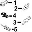
详细描述
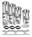
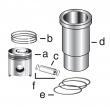
约翰迪尔林业摇摆机应用的发动机零件
设备型号 备注
2954D Piston (m) RE521616 Tier 2 & Tier 3
2954D Piston (m) RE515037 Tier 2 & Tier 3
2954D Piston (m) RE507758 Tier 2 & Tier 3
2954D Piston (m) RE515037 Tier 2 & Tier 3
3754D 9.0 Liter Tier 2 & Tier 3
2954D Piston (m) RE521616 Tier 2 & Tier 3
2954D Piston (m) RE515037 Tier 2 & Tier 3
2954D Piston (m) RE507758 Tier 2 & Tier 3
2954D Piston (m) RE515037 Tier 2 & Tier 3
3754D 9.0 Liter Tier 2 & Tier 3
约翰迪尔 6090 9.0L
|
|
||||||||||||||||||||||||||||
(*)带垫片。
(1)纸垫片。
(2)金属/橡胶垫圈。
(3)检查应用程序是否正确使用。
(4)与RE529972阀盖一起使用。
(5)与RE536705阀盖一起使用。
(6)法兰密封。
(7)检查正确的应用程序。
直销美国强鹿JOHN DEERE柴油机配件、发动机配件、发电机组: 3029DF120、3029TF158、3029TFU80、3029HFU70、4045HF280、4045TF002、3029DF128、30294045TF258、4045TF275、4045TF220、4045HF285、4045TF258、4045TFU70、4045HF285V07、4045TF220ouo1004,0000bc1 –19–26oct00–1/1 fuel filter/water separator assembly rg11164 –un–18oct00 fuel filter/water separator assembly a—fuel return (from fuel rail) b—fuel pressure sen*** c—fuel return (to fuel tank) d—fuel outlet (to supply pump) e—check valve f—water drain g—water in fuel sen*** h—fuel inlet (from fuel tank) i—fuel primer j—fuel temperature sen*** k—diagnostic test port torque specifications for fuel filter assembly are as follows: fuel filter assembly—specification fuel line orfs fittings—torque. 24 n?m (18 lb-ft) fitting (fuel return from rail)— torque . 33 n?m (24 lb-ft) fuel pressure sen***—torque 14 n?m (124 lb-in.) fitting (fuel pressure sen***)— torque 14 n?m (124 lb-in.) fitting (fuel return to tank)— torque . 33 n?m (24 lb-ft) fitting (fuel outlet to supply pump)—torque . 33 n?m (24 lb-ft) fitting (fuel inlet from tank)— torque . 33 n?m (24 lb-ft) fuel primer—torque 14 n?m (124 lb-in.) fuel primer-to-fuel filter housing adapter (single rail fuel system)—torque 11 n?m (97 lb-in.) fuel temperature sen***— torque 14 n?m (124 lb-in.) check valve&fitting—torque . 33 n?m (24 lb-ft) diagnostic test port&fitting— torque 14 n?m (124 lb-in.) filter housing plugs—torque 7 n?m (62 lb-in.) filter cap—torque. 11 n?m (100 lb-in.) water separator bowl—torque . 6 n?m (55 lb-in.) fuel filter return tube (inside filter housing)—torque 20 n?m (15 lb-ft) fuel filter assembly-to-bracket cap screws—torque 50 n?m (37 lb-ft) fuel filter bracket-to-cylinder block cap screws—torque 65 n?m (48 lb-ft) ctm188 (20mar01) 02-091-3 powertech 10.5 l & 12.5 l level 6 fuel system 032001 pn=57 single rail fuel system repair&adjustment 02 091 4 dpsg,ouo1004,1015 –19–24aug99–1/5 replacing fuel filter/water separator rg10302 –un–02sep99 filter cap remove old fuel filter element caution: if engine has been running, engine and fuel filter housing may be hot. 1. close fuel shut-off valve (if equipped). 2. clean entire area surrounding fuel filter assembly to keep debris from entering fuel system. 3. remove cap from fuel filter housing. if cap is too tight, a wrench/pliers may be used to loosen cap, as shown. dpsg,ouo1004,1015 –19–24aug99–2/5 rg10303 –un–02sep99 relieve vacuum 4. relieve vacuum in filter housing by operating hand primer until fuel filter “pops up”. if filter does not “pop up” after about 30 strokes of primer, a small screwdriver may be used, as shown, to carefully pry under filter flange to relieve vacuum in the housing. continued on next page ctm188 (20mar01) 02-091-4 powertech 10.5 l & 12.5 l level 6 fuel system 032001 pn=58 single rail fuel system repair&adjustment 02 091 5 dpsg,ouo1004,1015 –19–24aug99–3/5 rg10304 –un–02sep99 remove filter element 5. lift filter element up in housing until filter seal clears inlet tube inside housing. continue to hold filter suspended straight up in top of housing to drain fuel from filter. 6. allow fuel to drain completely from filter into housing. carefully begin rotating filter from housing, as shown, until completely upside down to ensure minimal leakage from fuel filter. 7. place filter in container suitable for diesel fuel. important: reusing fuel filter once removed from housing may result in trapped air in the filter, causing fuel to overflow from the filter housing during insertion of filter element and/or cause the engine to stall and not restart without additional system purging. continued on next page ctm188 (20mar01) 02-091-5 powertech 10.5 l & 12.5 l level 6 fuel system 032001 pn=59 single rail fuel system repair&adjustment 02 091 6 dpsg,ouo1004,1015 –19–24aug99–4/5 rg10351 –un–13sep99 water separator bowl a—strap wrench remove&install water separator bowl important: use the least amount of force as necessary with strap wrench when removing&installing separator bowl to prevent plastic bowl from cracking. 1. disconnect wiring connector from water-in-fuel sen***. 2. drain fuel from separator bowl. 3. position a strap wrench (a) as close as possible to top edge of separator bowl. while applying pressure with strap wrench, grip bowl&twist with other hand, as shown, to remove bowl. 4. install separator bowl&tighten by hand until seal makes contact. tighten to the following specification. specification water separator bowl-to-filter housing—torque 6 n?m (55 lb-in.) 5. connect wiring to water-in-fuel sen***. continued on next page ctm188 (20mar01) 02-091-6 powertech 10.5 l & 12.5 l level 6 fuel system 032001 pn=60 single rail fuel system repair&adjustment 02 091 7 dpsg,ouo1004,1015 –19–24aug99–5/5 rg10305 –un–02sep99 fuel level in filter housing a—maximum level 63 mm (2-1/2 in.) from top of housing b—minimum level 127 mm (5 in.) from top of housing install new fuel filter element 1. check to ensure that the fuel level in the filter housing is between the min (b)&max (a) fuel levels indicated on the outside of the housing&on the corresponding marks on the center tube. if the fuel is below the min level, carefully open the fuel supply shut-off valve a small amount (if equipped) to add fuel. operate the hand primer to add more fuel if required or if the unit is not equipped with a fuel supply shut-off valve. important: fuel level below the min indication may result in trapped air in the filter causing the engine to stall? restart without additional system purging. fuel level above the max indication may cause fuel to overflow from the filter housing during insertion of filter element. always use a new filter element whenever an existing element has been removed from filter housing. 2. insert new (dry) fuel filter into filter housing. 3. reinstall fuel filter cap&tighten by hand to the following specification. specification fuel filter cap/cover-to-housing—torque. 11 n?m (100 lb-in.) 4. open the fuel supply shut-off valve (if equipped). 5. restart engine&allow to run for 5 minutes minimum at slow idle. ctm188 (20mar01) 02-091-7 powertech 10.5 l & 12.5 l level 6 fuel system 032001 pn=61 single rail fuel system repair&adjustment 02 091 8 dpsg,ouo1004,1029 –19–26oct00–1/1 remove&install low pressure regulating valve rg10354 –un–17sep99 low pressure regulating valve rg10356 –un–17sep99 valve components a—o-ring b—valve seat c—low pressure regulating valve d—seal e—spring, low pressure (color coded red) f—o-ring g—valve housing 1. close fuel shut-off valve, if equipped. note: on high fuel tank applications without fuel shut-off valve, fuel tank return line must be pinched before disconnecting, then plugged, 2. disconnect fuel tank return line from filter housing and drain fuel into clean container. 3. remove low pressure regulating valve parts (a—g). to remove valve seat (b), use a standard wire tie strap with approximate 5/16 x 3/16 inch square head. insert tie strap head through bore of valve seat, rotate to catch lip of seat&remove seat. 4. clean&inspect all parts. replace all o-rings and seals. 5. install parts in reverse order. install valve seat (b) (o-ring end first) into bore of filter housing. make sure it is firmly seated in bore. install seal (d) with tapered edge of seal into lip of regulating valve (c). spring (e) is color coded red, identifying it as the low pressure spring. tighten valve housing (g) to specifications. specification low pressure regulating valve-to-filter housing—torque. 18 n?m (13 lb-ft) ctm188 (20mar01) 02-091-8 powertech 10.5 l & 12.5 l level 6 fuel system 032001 pn=62 single rail fuel system repair&adjustment 02 091 9 dpsg,ouo1004,1014 –19–26oct00–1/2 remove&install high pressure regulating valve rg11168 –un–30oct00 high pressure regulating valve a—screen b—o-ring c—high pressure regulating valve d—o-ring e—o-ring f—fuel temperature sen*** 1. close fuel shut-off valve, if equipped. note: on high fuel tank applications without fuel shut-off valve, fuel tank return line must be pinched before disconnecting, then plugged, 2. disconnect fuel tank return line from filter housing and drain fuel into clean container. 3. open valve on water separator bowl&drain filter housing. 4. remove fuel temperature sen*** (f). see remove and install fuel temperature sen*** in group 110. 5. remove high pressure regulating valve (c). 6. to remove screen (a), see remove&install 100 micron internal filter housing screen insert next in this group. note: high pressure regulating valve is not repairable. do not disassemble valve. if defective, replace entire assembly. 7. clean&inspect all parts. replace all o-rings. 8. install parts in reverse order. if removed, install screen (a). see remove and install 100 micron internal filter housing screen insert next in this group. tighten regulating valve to specifications. specification high pressure regulating valve-to-filter housing—torque 14 n?m (124 lb-in.) 9. install fuel temperature sen*** (f). see remove and install fuel temperature sen*** in group 110. ctm188 (20mar01) 02-091-9 powertech 10.5 l & 12.5 l level 6 fuel system 032001 pn=63 continued on next page single rail fuel system repair&adjustment 02 091 10 dpsg,ouo1004,1014 –19–26oct00–2/2 10. add fuel to filter housing between minimum and maximum marks on housing. fuel can be added by throttling the fuel shut-off valve (if equipped),/by removing cover&adding fuel from a clean container. ctm188 (20mar01) 02-091-10 powertech 10.5 l & 12.5 l level 6 fuel system 032001 pn=64 single rail fuel system repair&adjustment 02 091 11 dpsg,ouo1004,1030 –19–26oct00–1/1 remove&install 100 micron internal filter housing screen insert rg11168 –un–30oct00 high pressure regulating valve rg10358 –un–17sep99 remove screen a—100 micron screen b—o-ring c—high pressure regulating valve d—o-ring e—o-ring f—fuel temperature sen*** k—allen wrench with rubber band 1. remove fuel temperature sen*** (f). see remove and install fuel temperature sen*** in group 110. remove high pressure regulating valve (c). see remove&install high pressure regulating valve earlier in this group. important: if allen wrench is pushed too far into 10 micron screen during removal and installation, screen may be damaged. tie a rubber band (k) approximately 10 mm (3/8 in.) from end of allen wrench, as shown, to prevent screen damage. note: screen is approximately 91 mm (3-5/8 in.) up in bore of filter housing. use a long allen wrench. 2. attach a rubber band (k) on end of 5 mm allen wrench and remove 10 micron screen (a) from filter housing. 3. clean&inspect screen. 4. using allen wrench with rubber band, install screen in filter housing&tighten to the following specification. specification 100 micron internal filter housing screen—torque . 5 n?m (44 lb-in.) 5. install pressure regulating valve parts (b—d). see remove&install high pressure regulating valve earlier in this group. install fuel temperature sen*** parts (e)&(f). see remove and install fuel temperature sen*** in group 110. ctm188 (20mar01) 02-091-11 powertech 10.5 l & 12.5 l level 6 fuel system 032001 pn=65 single rail fuel system repair&adjustment 02 091 12 dpsg,ouo1004,1016 –19–18dec00–1/1 remove&install fuel filter check valve rg10307 –un–31aug99 fuel filter check valve a—o-ring b—check valve c—o-ring 1. close fuel shut-off valve (if equipped). 2. disconnect fuel line (shown disconnected)&remove check valve (b). remove o-rings (a)&(c) from both ends of check valve. 3. install check valve in filter housing&tighten to specifications. specification fuel filter check valve to fuel filter housing—torque . 33 n?m (24 lb-ft) 4. connect fuel line&tighten to specifications. specification fuel line-to-fuel filter check valve—torque. 24 n?m (18 lb-ft) 5. open fuel shut-off valve. dpsg,ouo1004,1032 –19–26oct00–1/1 remove&install primer pump rg10360 –un–30sep99 primer pump a—primer pump b—adapter 1. remove primer pump (a). 2. if required, remove adapter (b). 3. clean&inspect parts. 4. install primer pump&adapter with new o-rings and tighten to specifications. specification fuel primer (single rail fuel system)—torque 14 n?m (124 lb-in.) fuel primer-to-fuel filter housing adapter (single rail fuel system)—torque 11 n?m (97 lb-in.) ctm188 (20mar01) 02-091-12 powertech 10.5 l & 12.5 l level 6 fuel system 032001 pn=66 single rail fuel system repair&adjustment 02 091 13 dpsg,ouo1004,1000 –19–13aug99–1/2 remove&install single rail fuel supply pump rg10289 –un–20aug99 fuel supply pump rg10288 –un–23aug99 removing fuel supply pump a—supply pump outlet line c—fuel supply pump e—fitting f—mounting bracket b—fitting d—supply pump inlet line important: plug/cap all fuel system connections&passages as lines or components are removed to keep debris out using jdg998 fuel system cap plug kit. remove fuel supply pump note: fuel flow through cylinder head may vary by engine application. supply pump (a) may be mounted as shown with fuel entering the front left side of the cylinder head&exiting the back of the head. on some machine applications, the fuel supply pump is rotated 180°&the fuel lines on cylinder head are reversed, with fuel entering the back of the head&exiting the front left side of the head. add a reference mark (supply pump-to-cylinder head)&label fuel lines as they are disconnected, to ensure correct reinstallation of supply pump. 1. remove two fuel lines (a)&(d) connected to fuel supply pump. cap all lines&fittings to keep debris out of fuel system. 2. remove four cap screws securing supply pump to mounting bracket (f)&remove pump. remove and discard o-ring. note: fuel supply pump is not serviceable; replace pump if determined to be defective. 3. remove fittings (b)&(e) from pump&clean thoroughly if pump is to be replaced. install fuel supply pump 1. install fittings onto new pump using new o-rings. tighten fittings securely. 2. ensure that drive coupler set screw is tightened to specifications on supply pump drive shaft with end of shaft flush with coupler id. check drive coupler on camshaft drive pin also; adjust as needed. specification fuel supply pump and camshaft drive coupler set screws—torque . 4 n?m (3 lb-ft) ctm188 (20mar01) 02-091-13 powertech 10.5 l & 12.5 l level 6 fuel system 032001 pn=67 continued on next page single rail fuel system repair&adjustment 02 091 14 dpsg,ouo1004,1000 –19–13aug99–2/2 3. position new rubber spider (vibration ab***ber) on drive coupler. position new o-ring on face of supply pump. 4. if removed, apply ar54749 soap lubricant to new o-ring on supply pump mounting bracket (f) and install. tighten mounting bracket cap screws to specifications. specification fuel supply pump mounting bracket cap screws—torque 50 n?m (37 lb-ft) 5. install fuel supply pump with rubber spider properly meshed with coupler on rear of camshaft. 6. install four cap screws&tighten to specifications. specification fuel supply pump-to-bracket— torque. 25 n?m (18 lb-ft) important: before connecting orfs fuel line fittings, be sure o-ring is correctly positioned in the groove of fitting. tighten fitting only to specified torque. do not overtighten. 7. install two fuel lines&tighten to specifications. specification fuel line orfs fittings— torque. 24 n?m (18 lb-ft) ctm188 (20mar01) 02-091-14 powertech 10.5 l & 12.5 l level 6 fuel system 032001 pn=68 single rail fuel system repair&adjustment 02 091 15 dpsg,ouo1004,1001 –19–26oct00–1/5 remove&install electronic unit injectors (single rail fuel system) rg8279 –un–05dec97 unit injector clamp screws a—clamp cap screws important: electronic unit injectors on dual rail fuel systems are different than injectors on single rail systems. use the appropriate injector for engine/fuel system applications. additionally, early single rail fuel systems for engines s.n. (— 29999) use different injectors than later single rail systems for engines s.n. (30000— ). replace injector with the same type removed. do not intermix injectors. see parts catalog for correct applications. 1. remove rocker arm cover. see remove and install rocker arm cover in ctm100, section 02, group 020. 2. remove rocker arm shaft assembly. see remove rocker arm assembly in ctm100, section 02, group 020. 3. disconnect fuel lines&drain fuel from lines&fuel rail in cylinder head. 4. reconnect lines (or install cap plugs from jdg998 fuel system cap plug kit) to keep debris out of fuel system. 5. remove injector hold-down clamp cap screws (a). continued on next page ctm188 (20mar01) 02-091-15 powertech 10.5 l & 12.5 l level 6 fuel system 032001 pn=69 single rail fuel system repair&adjustment 02 091 16 dpsg,ouo1004,1001 –19–26oct00–2/5 rg8280 –un–05dec97 position prybar rg8281 –un–05dec97 removing unit injector rg10311 –un–02sep99 unit injector removed a—hold-down clamp b—prybar c—injector o-rings 6. pry upward on the injector hold-down clamp (a) against cylinder head using a prybar (b) as shown. 7. remove injector&clamp from cylinder head. label injector for installation in same cylinder location as removed. 8. immediately plug injector bore with clean cap plug to keep debris out of fuel system. 9. remove injector o-rings (c)&discard. 10. store injector in a clean, lint-free container. continued on next page ctm188 (20mar01) 02-091-16 powertech 10.5 l & 12.5 l level 6 fuel system 032001 pn=70 single rail fuel system repair&adjustment 02 091 17 dpsg,ouo1004,1001 –19–26oct00–3/5 rg10312 –un–02sep99 installing unit injector a—o-rings install electronic unit injectors 1. remove cap plug from injector bore in cylinder head. clean entire sleeve using a clean, lint-free cloth wrapped around a wooden stick. 2. install three new o-rings (a) on unit injector body. lubricate o-rings with clean engine oil/amojell lubricant. continued on next page ctm188 (20mar01) 02-091-17 powertech 10.5 l & 12.5 l level 6 fuel system 032001 pn=71 single rail fuel system repair&adjustment 02 091 18 dpsg,ouo1004,1001 –19–26oct00–4/5 rg10249 –un–30jul99 injector hold-down clamp screws rg9574 –un–04dec98 torque-turn eui a—clamp cap screw b—ratchet handle important: press on top of injector plunger with palm of hand to properly seat o-rings and center injector between valve springs. note: new eui hold-down clamp cap screws have pre-applied sealant. 3. install unit injector with hold-down clamp into same cylinder as removed (solenoid outward toward exhaust manifold side of engine at equal distance between exhaust valve springs). apply loctite? 242 thread lock&sealer to used hold-down cap screw. initially tighten cap screw to specifications. specification electronic unit injector hold-down clamp cap screws— initial torque 20 n?m (15 lb-ft) 4. mark head of cap screw (a) at twelve o’clock position (viewed from rear) using a paint stick. 5. install 13 mm swivel socket on head of cap screw. position ratchet handle (b) parallel with centerline of engine camshaft/crankshaft. torque-turn cap screw to the following specification. specification electronic unit injector hold-down clamp cap screws— final torque-turn 90—100° 6. remove socket from head of cap screw&verify that mark has been tightened/turned at least 90° but not more than 100° from its original position. loctite is a registered trademark of loctite corp. continued on next page ctm188 (20mar01) 02-091-18 powertech 10.5 l & 12.5 l level 6 fuel system 032001 pn=72 single rail fuel system repair&adjustment 02 091 19 dpsg,ouo1004,1001 –19–26oct00–5/5 rg10294 –un–27aug99 wiring terminal nuts a—retaining nuts important: do not use red/blue loctite? on solenoid studs. bonding strength is too high for small studs, making future removal impossible without twisting off stud. 7. reconnect injector solenoid wiring leads onto solenoid studs. apply loctite? 222 small screw thread locker (ty24311) to studs&tighten retaining nuts (a) to specifications. specification electronic unit injector wiring harness connector nuts—torque. 2 n?m (18 lb-in.) 8. install valve bridges, push tubes,&rocker arm assembly. adjust valve stem-to-bridge clearances. see install rocker arm assembly in ctm100, section 02, group 020. 9. if removed/loosened, tighten all harness&line clamps to specifications. specification fuel line clamps—torque 5 n?m (44 lb-in.) electronic unit injector harness-to-shaft clamps— torque . 35 n?m (26 lb-ft) electronic unit injector wiring connector bracket-to-rear of head—torque . 25 n?m (18 lb-ft) 10. adjust electronic unit injector preload as detailed later in this group. loctite is a registered trademark of loctite corp. ctm188 (20mar01) 02-091-19 powertech 10.5 l & 12.5 l level 6 fuel system 032001 pn=73 single rail fuel system repair&adjustment 02 091 20 rg,rg34710,263 –19–03nov00–1/3 adjust electronic unit injector preload rg8228a –un–05dec97 jdg971 timing pin in camshaft rg8227d –un–05dec97 jdg971 timing pin in crankshaft rg11165 –un–30oct00 camshaft timing slot a—jdg971 timing pin b—jdg820 flywheel turning tool c—jdg971 timing pin d—single timing slot e—double timing slot 1. remove plug from cylinder block&install jdg820 flywheel turning tool (b). important: timing pin must be installed in slot of camshaft first. then install second timing pin in crankshaft slot by carefully rocking flywheel back and forth. 2. rotate engine flywheel in running direction (counterclockwise as viewed from rear) until jdg971 timing pin (a) engages single timing slot (d) in camshaft. the proper timing slot can be found by viewing camshaft timing lobe through camshaft timing pin bore while rotating engine. the double timing slot (e) will be at approximately 11 o’clock (viewed from rear of engine) when pin is installed in slot (d).this ensures that engine is locked at tdc of no. 1 cylinder’s compression stroke. intake&exhaust rocker arms on no. 1 cylinder should be loose. 3. remove threaded plug from crankshaft timing hole below oil cooler&filter housing assembly. important: do not insert timing pin full depth into cylinder block crankshaft timing hole when rotating engine flywheel until double slot on camshaft timing lobe is at approximately 11 o’clock (viewed from rear of engine) to avoid crankshaft counterweight bending timing pin. 4. slightly move engine flywheel back&forth with turning tool until a second jdg971 timing pin (c) can be installed in slot in crankshaft. this ensures that camshaft&crankshaft are in sync (properly timed). ctm188 (20mar01) 02-091-20 powertech 10.5 l & 12.5 l level 6 fuel system 032001 pn=74 continued on next page single rail fuel system repair&adjustment 02 091 21 rg,rg34710,263 –19–03nov00–2/3 if timing pin does not enter crankshaft timing slot, crankshaft is not properly timed with camshaft. crankshaft must be timed to camshaft. see check and adjust camshaft-to-crankshaft timing in ctm100, section 02, group 050. rg,rg34710,263 –19–03nov00–3/3 rg8270 –un–05dec97 unit injector adjusting screw a—lock nut b—adjusting screws 5. loosen lock nut (a)&loosen cylinders nos. 3, 5, and 6 injector rocker arm adjusting screws (b) to relieve tension. 6. slowly tighten adjusting screw until rocker arm roller contacts camshaft lobe at 0.0 clearance. 7. tighten adjusting screw an additional 1/2 turn (180°) to preload injector. tighten adjusting screw lock nut to specifications while holding adjusting screw stationary. specification electronic unit injector adjusting screw lock nut—torque 65 n?m (48 lb-ft) 8. remove both timing lock pins, rotate crankshaft one full revolution (360°)&pin crankshaft only. engine will now be locked at no. 6 tdc. 9. set injector preload on cylinders nos. 1, 2,&4. 10. install plug in timing pin hole in block&tighten to specifications. specification timing pin plug in cylinder block—torque. 33 n?m (24 lb-ft) ctm188 (20mar01) 02-091-21 powertech 10.5 l & 12.5 l level 6 fuel system 032001 pn=75 single rail fuel system repair&adjustment 02 091 22 dpsg,ouo1004,1031 –19–20nov00–1/1 replace electronic unit injector o-rings rg10313 –un–02sep99 unit injector&clamp a—o-rings 1. the electronic unit injector’s three external o-rings (a) must be replaced whenever injector is removed. 2. fuel system diagnosis will determine if unit injector is not functioning properly. refer to section 04, groups 150&160, as required. 3. replaced unit injectors will be returned by your authorized servicing dealer to the manufacturer for testing&rebuilding. dpsg,ouo1004,1028 –19–15sep99–1/1 replace electronic unit injector thrust sleeve, pad&o-ring rg10353 –un–16sep99 electronic unit injector a—thrust socket b—o-ring c—thrust pad 1. using an o-ring pick, remove o-ring (b). 2. remove thrust socket (a)&pad (c). 3. coat parts with clean engine oil&install in reverse order. ctm188 (20mar01) 02-091-22 powertech 10.5 l & 12.5 l level 6 fuel system 032001 pn=76 single rail fuel system repair&adjustment 02 091 23 dpsg,ouo1004,1004 –19–26oct00–1/1 bleed fuel system rg10309 –un–02sep99 bleed fuel system a—diagnostic port b—hand primer c—water drain valve note: under normal conditions, fuel system bleeding is not required. priming system with hand primer (b) is normally sufficient. if necessary to bleed the system, use the following procedure. 1. drain water&contaminants from clear water separator sediment bowl by opening drain valve (c) and operating primer (b) until bowl is clear of water. 2. close drain valve (c). 3. attach a dr fitting&clear drain line to diagnostic fitting (a)&place end of line in suitable container for diesel fuel. 4. pump hand primer (b) until a steady flow of fuel (without bubbles) comes out of line. 5. disconnect line from diagnostic fitting. 6. start engine&run for five minutes at slow idle. ctm188 (20mar01) 02-091-23 powertech 10.5 l & 12.5 l level 6 fuel system 032001 pn=77 single rail fuel system repair&adjustment 02 091 24 ctm188 (20mar01) 02-091-24 powertech 10.5 l & 12.5 l level 6 fuel system 032001 pn=78 group 110 electrical engine control repair&adjustment 02 110 1 ouo1004,0000c41 –19–20dec00–1/2 john deere level 6 electronic control system rg11177 –un–20dec00 electronic control system a—engine control unit (ecu) d—fuel temperature sen*** g—oil pressure sen*** l—camshaft position sen*** b—throttle position sen*** e—manifold air temperature h—fuel pressure sen***1 m—diagnostic reader c—coolant temperature (mat) sen*** i—water-in-fuel sen***1 n—vehicle output monitor sen*** (1/2 used) f—manifold absolute pressure j—crankshaft position sen*** (map) sen*** k—electronic unit injector (6 used) 1 sen*** is on later model engines with single fuel filter assembly. ctm188 (20mar01) 02-110-1 powertech 10.5 l & 12.5 l level 6 fuel system 032001 pn=79 continued on next page electrical engine control repair&adjustment 02 110 2 ouo1004,0000c41 –19–20dec00–2/2 note: electronic control system diagnosis will determine if a sen*** is not functioning properly. refer section 04, groups 150 and 160 as required. important: do not pressure wash the engine control unit (ecu). before welding on engines with ecu, protect the ecu from high-current damage as follows: 1. disconnect ecu-to-vehicle frame ground connection. 2. disconnect all other connectors from ecu. 3. connect welder ground close to welding point&make sure ecu and other electrical components are not in the ground path. the ecu mounting bracket is attached to the cylinder block. if removed, reinstall&tighten mounting bracket cap screws to the following specifications. specification ecu mounting bracket-to-cylinder block lower cap screws—torque 68 n?m (55 lb-ft) ecu mounting bracket-to-cylinder block upper front cap screw— torque. 110 n?m (81 lb-ft) rg,rg34710,269 –19–13aug99–1/1 remove&install coolant temperature sen*** rg8550 –un–10dec97 ect sen*** a—coolant temperature sen*** b—thermostat housing note: your engine may be equipped with either one or two coolant temperature sen***(s) (a). the ecu monitors coolant temperature for engine protection purposes&starting. using the coolant temperature signal, the ecu will derate engine power as coolant temperature becomes excessive. the ecu will also adjust fuel delivery during start-up during low coolant temperature conditions. 1. disconnect coolant temperature sen*** wiring connector&remove sen*** from thermostat housing (b). 2. coat sen*** o-ring with jdt405 high temperature grease&install sen*** in thermostat housing. tighten to specifications. specification coolant temperature sen***— torque 10 n?m (7.5 lb-ft) 3. install sen*** wiring connector. 恩施强鹿柴油发动机出油阀公司,阿坝JohnDeere气门油封R527285厂家供货,松原强鹿柴油机曲轴前油封RE54073价格行情,惠州强鹿RE55900凸轮轴多少钱,宜昌强鹿活塞销R502755厂家供货,杭州johndeere约翰迪尔强鹿柴油机活塞冷却喷咀市场报价,黄南强鹿发动机水泵价格行情,亳州约翰迪尔强鹿气门油封R527285供货商,玉林约翰迪尔活塞RE53265哪家好,ctm188 (20mar01) 02-110-2 powertech 10.5 l & 12.5 l level 6 fuel system 032001 pn=80 electrical engine control repair&adjustment 02 110 3 rg,rg34710,270 –19–13aug99–1/1 remove&install fuel temperature sen*** (dual rail system) rg8549 –un–10dec97 fuel temperature sen*** a—fuel manifold the ecu monitors fuel temperature to determine fuel density&adjust delivery as necessary. 1. disconnect fuel temperature sen*** wiring connector and remove sen*** from fuel manifold (a). note: plug bore with clean cap plug after removal of sen***. 2. coat sen*** o-ring with jdt405 high temperature grease&install sen*** in fuel manifold. tighten to specifications. specification fuel temperature sen***-to-fuel manifold (dual rail fuel system)—torque 10 n?m (7.5 lb-ft) 3. install sen*** wiring connector. dpsg,ouo1004,1008 –19–23aug99–1/1 remove&install fuel temperature sen*** (single rail system) rg10299 –un–27aug99 fuel temperature sen*** the ecu monitors fuel temperature to determine fuel density&adjust delivery as necessary. 1. disconnect fuel temperature sen*** wiring connector and remove sen*** from fuel filter housing. note: plug bore with clean cap plug after removal of sen***. 2. coat sen*** o-ring with jdt405 high temperature grease&install sen*** in fuel filter housing. tighten to specifications. specification fuel temperature sen***-to-fuel filter housing (single rail fuel system)—torque. 14 n?m (10 lb-ft) 3. install sen*** wiring connector. ctm188 (20mar01) 02-110-3 powertech 10.5 l & 12.5 l level 6 fuel system 032001 pn=81 electrical engine control repair&adjustment 02 110 4 dpsg,ouo1004,1010 –19–18dec00–1/1 remove&install fuel pressure sen*** (single rail fuel system) rg10298 –un–27aug99 fuel pressure sen*** (later engines with single rail fuel systems only) the ecu monitors fuel pressure to protect the electronic unit injectors from low fuel pressure conditions. the ecu will generate a diagnostic trouble code (or warning light in some applications) when a low fuel pressure condition exists. 1. disconnect fuel pressure sen*** wiring connector and remove sen*** from fuel filter housing. note: plug bore with clean cap plug after removal of sen***. 2. coat sen*** o-ring with jdt405 high temperature grease&install sen*** in fuel filter housing. tighten to specifications. specification fuel pressure sen***-to-fuel filter housing (single rail fuel system)—torque. 14 n?m (10 lb-ft) 3. install sen*** wiring connector. ctm188 (20mar01) 02-110-4 powertech 10.5 l & 12.5 l level 6 fuel system 032001 pn=82 electrical engine control repair&adjustment 02 110 5 dpsg,ouo1004,1011 –19–18dec00–1/1 remove&install water-in-fuel sen*** (single rail fuel system) rg10297 –un–27aug99 water-in-fuel sen*** (later engines with single rail fuel systems only) the ecu monitors water in fuel to protect the electronic unit injectors. the ecu will generate a diagnostic trouble code (or warning light in some applications) when water is detected in the fuel. 1. disconnect water in fuel sen*** wiring connector and remove sen*** from water separator bowl. note: plug bore with clean cap plug after removal of sen***. 2. coat sen*** o-ring with jdt405 high temperature grease&install sen*** in water separator bowl.tighten to specifications. specification water-in-fuel sen***-to-water separator bowl (single rail fuel system)—torque. 14 n?m (10 lb-ft) 3. install sen*** wiring connector. ctm188 (20mar01) 02-110-5 powertech 10.5 l & 12.5 l level 6 fuel system 032001 pn=83 electrical engine control repair&adjustment 02 110 6 dpsg,ouo1004,1012 –19–26oct00–1/1KEY PART NO. PART NAME QTY SERIAL NO. F F F REMARKS
1 RE65265 HAND PRIMER 1 X (SUB FOR RE48048)
2 R54025 WASHER 1 X
3 R26448 O-RING 2 X
4 RE34128 ELBOW FITTING 1 X (A)
RE10258 ELBOW FITTING 1 X (B)
5 R67879 GASKET 1 X
6 RE46252 FUEL PUMP 1 X (ROBERT BOSCH)
7 R93008 WASHER NA X
8 R83489 FITTING NA X
(A) INLET (B) OUTLET
ENTREE SORTIE
EINLASS AUSCLASSE
ENTRATA USCITA
ENTRADA SALIDA
INLOPP UTLOPP
KEY PART NO. PART NAME QTY SERIAL NO. F F F REMARKS
1 RE507268 FUEL LINE 1 X NO. 6
2 RE507267 FUEL LINE 1 X NO. 5
3 RE507266 FUEL LINE 1 X NO. 4
4 RE507265 FUEL LINE 1 X NO. 3
5 R120185 BOLT 4 X
R120181 STRAP 4 X
R120182 STRAP 4 X
R58186 CLAMP 4 X
6 RE507264 FUEL LINE 1 X NO. 2
7 RE507263 FUEL LINE 1 X NO. 1
8 R71212 CLAMP 1 X
R59297 HALF CLAMP 2 X
R120186 BOLT 2 X
R120183 STRAP 1 X
R120184 STRAP 1 X
9 R71212 CLAMP 1 X
R59297 HALF CLAMP 2 X
R120186 BOLT 2 X
R120183 STRAP 1 X
R120184 STRAP 1 X
R120186 BOLT 2 X
10 RE55662 ABSORBER 1 X
11 R59297 HALF CLAMP 2 X
R120185 BOLT 1 X
R120183 STRAP 2 X
12 24H1884 WASHER 1 X 13/32" X 13/16" X 0.120" 13/32" X
13/16" X 0.120"
13 19M7166 CAP SCREW 1 X M10 X 20
14 RE64265 INJECTION NOZZLE 6 X (A) (DENSO)
15 R84472 WASHER 6 X 7.360 X 18.160 X 2 MM (0.290" X 0.715"
X 0.079") 7.360 X 18.160 X 2 MM
(0.290" X 0.715" X 0.079")
16 RE500803 FUEL LINE 1 X
17 AR85519 PLUG 1 X
18 R51937 TUBE NUT 1 X
19 R79604 TUBE NUT 6 X
20 R504057 O-RING 6 X (SUB FOR T44604)
21 RE501970 ADAPTER 6 X
22 RE71255 PIPE PLUG 1 X
(A) 1 RED RING
KEY PART NO. PART NAME QTY SERIAL NO. F F F REMARKS
1 R68035 NUT 1 X
2 R69089 O-RING 1 X
3 R115369 NOZZLE HOLDER 1 X
4 R68036 SHIM AR X 0.70MM (.028")
R90544 SHIM AR X 0.725MM (.0285")
R68037 SHIM AR X 0.75MM (.030")
R90543 WASHER AR X 0.775MM (.0305")
R68038 WASHER AR X 0.80MM (.032")
R90542 WASHER AR X 0.825MM (.0324")
R68039 WASHER AR X 0.85MM (.034")
R90541 WASHER AR X 0.875MM (.0344")
R68040 WASHER AR X 0.90MM (.035")
R90540 WASHER AR X 0.925MM (.0364")
R68041 WASHER AR X 0.95MM (.037")
R90539 WASHER AR X 0.0975MM (.0383")
R68042 WASHER AR X 1.00MM (.039")
R90538 WASHER AR X 1.025MM (.0403")
R68043 WASHER AR X 1.05MM (.041")
R90537 WASHER AR X 1.075MM (.0423")
R68044 WASHER AR X 1.10MM (.043")
R90536 WASHER AR X 1.125MM (.0443")
R68045 WASHER AR X 1.15MM (.045")
R90535 WASHER AR X 1.175MM (.0462")
R68046 WASHER AR X 1.20MM (.047")
R90534 WASHER AR X 1.225MM (.0482")
R68047 WASHER AR X 1.25MM (.049")
R90533 WASHER AR X 1.275MM (.0502")
R68048 WASHER AR X 1.30MM (.051")
R90532 WASHER AR X 1.325MM (.0522")
R68049 WASHER AR X 1.35MM (.053")
R90531 WASHER AR X 1.375MM (.0541")
R68050 WASHER AR X 1.40MM (.055")
R90530 WASHER AR X 1.425MM (.0561")
R68051 WASHER AR X 1.45MM (.057")
R90529 WASHER AR X 1.475MM (.0580")
R68052 WASHER AR X 1.50MM (.059")
5 R115368 SPRING 1 X
6 R94410 SEAT 1 X
7 R94412 PLATE 1 X
8 RE64266 NOZZLE 1 X (7 X 0.210)
9 R127176 NUT 1 X
10 R84472 WASHER 1 X
11 RE64265 INJECTION NOZZLE 6 X (A) (DENSO)
(A) 1 RED RING
400-100-8969 15088860848
0574-26871589 15267810868
0574-26886646 15706865167
0574-26871569 18658287286


 English
 Espaol
 Franais
 阿拉伯
阿拉伯 中文(简)
中文(简) Deutsch
 Italiano
 Português
 日本
日本 韩国
韩国 български
 hrvatski
 esky
esky Dansk
Dansk Nederlands
 suomi
suomi Ελληνικ
 印度
印度 norsk
norsk Polski
 Roman
Roman русский
 Svenska
