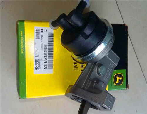
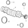
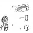
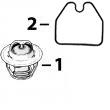
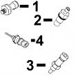
详细描述
约翰迪尔挖掘机应用的发动机零件
设备型号
备注
490
Large pin, O'rings on block, Con Rod (m): R51727, R80034, From ESN 275,484
70
Con Rod (m): R80034, Piston (m): RE30250
70D
Con Rod (m): R80034, Piston (m): RE30250
290D
Con Rod (m): R80034, Piston (m): RE30250
490D
Large pin
493D
Large pin
495D
(no special remarks)
590D
(no special remarks)
595D
(no special remarks)
595
(no special remarks)
490E
(no special remarks)
290D
Liter designated, Con Rod (m): R80034, Piston (m): RE30250, RE18697
70D
Liter designated, Con Rod (m): R80034, Piston (m): RE30250, RE18697
490D
Liter designated
493D
Liter designated
490E
Liter designated
495D
Liter designated
590D
Liter designated
595D
Liter designated
50D
88mm Bore Non Turbo
690
To ESN 335,845, Block (m): R43310, R45980, R47020, R47110
690A
To ESN 335,845, Block (m): R43310, R45980, R47020, R47110
690B
From ESN 335,846, Block (m): R49470, R49650, R59850, R72128, R87558
690D
(no special remarks)
690E
(no special remarks)
790E
(no special remarks)
892D
Con Rod (m) R71074 (P/N AR93341)
690C
Con Rod (m) R71074 (P/N AR93341)
690C
Con.Rod (m) R71074 (P/N AR93341)
790D
Con.Rod (m) R71074 (P/N AR93341)
892D
Con.Rod (m) R71074 (P/N AR93341)
890
Mid, Con Rod (m): R63959
890A
Mid, Con Rod (m): R63959
890
Late, Con Rod (m): R63959
890A
Late, Con Rod (m): R63959
992D
Late, Con Rod (m): R63959
992E
Late, Con Rod (m): R63959
690D
Liter designated
690E
Liter designated
790E
Liter designated
892E
Low Ring Piston, Con Rod (m): R71074 (P/N AR93341)
792D
High Ring Piston, Con Rod (m): R71074 (P/N AR93341)
792LC
High Ring Piston, Con Rod (m): R71074 (P/N AR93341)
330LC
Piston (m) RE507758 Tier 2 & Tier 3
230LCR
Piston (m) RE59277, RE505100
330 LC
High Compression Piston. To ESN 199,999. Tier 1
370C
Piston (m) RE521616 Tier 2 & Tier 3
330LCR
Piston (m) RE507758 Tier 2 & Tier 3
200LC
Piston (m) RE55512, RE505102
330 LCR
High Compression Piston. To ESN 199,999. Tier 1
370
Piston (m) RE515037 Tier 2 & Tier 3
370C
Piston (m) RE507758 Tier 2 & Tier 3
200LL
Piston (m) RE55512, RE505102
370 C
High Compression Piston. To ESN 199,999. Tier 1
330C
Piston (m) RE515037 Tier 2 & Tier 3
370
Piston (m) RE515037 Tier 2 & Tier 3
230LC
Piston (m) RE55512, RE505102
330CLC
High Compression Piston. From ESN 200,000. Tier 2.
330C LC
Piston (m) RE515037 Tier 2 & Tier 3
330C
Piston (m) RE515037 Tier 2 & Tier 3
270LC
Piston (m) RE55512, RE505102
370C
High Compression Piston. From ESN 200,000. Tier 2.
330LC
Piston (m) RE515037 Tier 2 & Tier 3
330C LC
Piston (m) RE515037 Tier 2 & Tier 3
698G
Piston (m) RE55512, RE505102
350DLC
9.0 Liter Tier 2 & Tier 3
330LCR
Piston (m) RE515037 Tier 2 & Tier 3
330LC
Piston (m) RE515037 Tier 2 & Tier 3
370
Piston (m) RE521616 Tier 2 & Tier 3
350GLC
9.0 Liter Tier 2 & Tier 3
370C
Piston (m) RE515037 Tier 2 & Tier 3
330LCR
Piston (m) RE515037 Tier 2 & Tier 3
330C
Piston (m) RE521616 Tier 2 & Tier 3
380GLC
9.0 Liter Tier 2 & Tier 3
370
Piston (m) RE507758 Tier 2 & Tier 3
370C
Piston (m) RE515037 Tier 2 & Tier 3
330C LC
Piston (m) RE521616 Tier 2 & Tier 3
E330LC
9.0 Liter Tier 2 & Tier 3
330C
Piston (m) RE507758 Tier 2 & Tier 3
370
High Compression Piston. To ESN 199,999. Tier 1
330LC
Piston (m) RE521616 Tier 2 & Tier 3
E360
9.0 Liter Tier 2 & Tier 3
330C LC
Piston (m) RE507758 Tier 2 & Tier 3
330C LC
High Compression Piston. To ESN 199,999. Tier 1
330LCR
Piston (m) RE521616 Tier 2 & Tier 3
80
98mm Bore Non Turbo Direct Injection
约翰迪尔挖掘机应用的发动机零件
| 设备型号 | 备注 |
|---|---|
| 490 | Large pin, O'rings on block, Con Rod (m): R51727, R80034, From ESN 275,484 |
| 70 | Con Rod (m): R80034, Piston (m): RE30250 |
| 70D | Con Rod (m): R80034, Piston (m): RE30250 |
| 290D | Con Rod (m): R80034, Piston (m): RE30250 |
| 490D | Large pin |
| 493D | Large pin |
| 495D | (no special remarks) |
| 590D | (no special remarks) |
| 595D | (no special remarks) |
| 595 | (no special remarks) |
| 490E | (no special remarks) |
| 290D | Liter designated, Con Rod (m): R80034, Piston (m): RE30250, RE18697 |
| 70D | Liter designated, Con Rod (m): R80034, Piston (m): RE30250, RE18697 |
| 490D | Liter designated |
| 493D | Liter designated |
| 490E | Liter designated |
| 495D | Liter designated |
| 590D | Liter designated |
| 595D | Liter designated |
| 50D | 88mm Bore Non Turbo |
| 690 | To ESN 335,845, Block (m): R43310, R45980, R47020, R47110 |
| 690A | To ESN 335,845, Block (m): R43310, R45980, R47020, R47110 |
| 690B | From ESN 335,846, Block (m): R49470, R49650, R59850, R72128, R87558 |
| 690D | (no special remarks) |
| 690E | (no special remarks) |
| 790E | (no special remarks) |
| 892D | Con Rod (m) R71074 (P/N AR93341) |
| 690C | Con Rod (m) R71074 (P/N AR93341) |
| 690C | Con.Rod (m) R71074 (P/N AR93341) |
| 790D | Con.Rod (m) R71074 (P/N AR93341) |
| 892D | Con.Rod (m) R71074 (P/N AR93341) |
| 890 | Mid, Con Rod (m): R63959 |
| 890A | Mid, Con Rod (m): R63959 |
| 890 | Late, Con Rod (m): R63959 |
| 890A | Late, Con Rod (m): R63959 |
| 992D | Late, Con Rod (m): R63959 |
| 992E | Late, Con Rod (m): R63959 |
| 690D | Liter designated |
| 690E | Liter designated |
| 790E | Liter designated |
| 892E | Low Ring Piston, Con Rod (m): R71074 (P/N AR93341) |
| 792D | High Ring Piston, Con Rod (m): R71074 (P/N AR93341) |
| 792LC | High Ring Piston, Con Rod (m): R71074 (P/N AR93341) |
| 330LC | Piston (m) RE507758 Tier 2 & Tier 3 |
| 230LCR | Piston (m) RE59277, RE505100 |
| 330 LC | High Compression Piston. To ESN 199,999. Tier 1 |
| 370C | Piston (m) RE521616 Tier 2 & Tier 3 |
| 330LCR | Piston (m) RE507758 Tier 2 & Tier 3 |
| 200LC | Piston (m) RE55512, RE505102 |
| 330 LCR | High Compression Piston. To ESN 199,999. Tier 1 |
| 370 | Piston (m) RE515037 Tier 2 & Tier 3 |
| 370C | Piston (m) RE507758 Tier 2 & Tier 3 |
| 200LL | Piston (m) RE55512, RE505102 |
| 370 C | High Compression Piston. To ESN 199,999. Tier 1 |
| 330C | Piston (m) RE515037 Tier 2 & Tier 3 |
| 370 | Piston (m) RE515037 Tier 2 & Tier 3 |
| 230LC | Piston (m) RE55512, RE505102 |
| 330CLC | High Compression Piston. From ESN 200,000. Tier 2. |
| 330C LC | Piston (m) RE515037 Tier 2 & Tier 3 |
| 330C | Piston (m) RE515037 Tier 2 & Tier 3 |
| 270LC | Piston (m) RE55512, RE505102 |
| 370C | High Compression Piston. From ESN 200,000. Tier 2. |
| 330LC | Piston (m) RE515037 Tier 2 & Tier 3 |
| 330C LC | Piston (m) RE515037 Tier 2 & Tier 3 |
| 698G | Piston (m) RE55512, RE505102 |
| 350DLC | 9.0 Liter Tier 2 & Tier 3 |
| 330LCR | Piston (m) RE515037 Tier 2 & Tier 3 |
| 330LC | Piston (m) RE515037 Tier 2 & Tier 3 |
| 370 | Piston (m) RE521616 Tier 2 & Tier 3 |
| 350GLC | 9.0 Liter Tier 2 & Tier 3 |
| 370C | Piston (m) RE515037 Tier 2 & Tier 3 |
| 330LCR | Piston (m) RE515037 Tier 2 & Tier 3 |
| 330C | Piston (m) RE521616 Tier 2 & Tier 3 |
| 380GLC | 9.0 Liter Tier 2 & Tier 3 |
| 370 | Piston (m) RE507758 Tier 2 & Tier 3 |
| 370C | Piston (m) RE515037 Tier 2 & Tier 3 |
| 330C LC | Piston (m) RE521616 Tier 2 & Tier 3 |
| E330LC | 9.0 Liter Tier 2 & Tier 3 |
| 330C | Piston (m) RE507758 Tier 2 & Tier 3 |
| 370 | High Compression Piston. To ESN 199,999. Tier 1 |
| 330LC | Piston (m) RE521616 Tier 2 & Tier 3 |
| E360 | 9.0 Liter Tier 2 & Tier 3 |
| 330C LC | Piston (m) RE507758 Tier 2 & Tier 3 |
| 330C LC | High Compression Piston. To ESN 199,999. Tier 1 |
| 330LCR | Piston (m) RE521616 Tier 2 & Tier 3 |
| 80 | 98mm Bore Non Turbo Direct Injection |
约翰迪尔 6081 低压缩活塞
|
|
|||||||||||||||||||||||||||
(1)用螺旋油泵驱动齿轮。 不要与HPCR燃油系统一起使用。
(2)带直油泵传动齿轮。
(3)纸垫片
(4)金属/橡胶垫圈。
(5)套件中均包含前部密封件。
(6)检查应用程序是否正确使用。
强鹿JOHN DEERE柴油机配件、发动机配件、发电机组:
P124866、P124867、P551130、P777638、P181099、P772579、P827653、P771548、P771548、P827653、P772579、P772580、P829333、P13194、P550388、C125017、C125004、P772579、C085001、C085002、C085003、C085004、ECB105012、C105003、AF1913、AF4539、C105004、RE533026diagnostics&tests 04 160 212 dpsg,rg40854,225 –19–30jun99–1/1 level 6 ecu - dtc spn 652 fmi 5 cylinder #2 eui circuit open rg10387 –19–23nov99 important: do not force probes into connector terminals/damage will result. use jt07328 connector adapter test kit to make measurements in connectors. this will ensure that terminal damage does not occur. eui (electronic unit injector) ? the fuel in 10.5 l&12.5 l engines is delivered by 6 (one for each cylinder) electronic unit injectors (euis). the euis are mounted in they cylinder head, under the valve cover, so that they spray directly into the center of the cylinder bore. each eui is an injection pump&injector combined, operating at much higher pressures than standard in-line or rotary injection pumps. the ecu controls the start of injection&the amount of fuel injected by turning the solenoid in the eui valve housing on&off which in turn opens&closes the eui spill valve. ? power is supplied to the euis for cylinders 1, 2, and 3 by a common wire,&to the euis for cylinders 4, 5,&6 by a different common wire. the ecu energizes&deenergizes the solenoids of individual euis by closing&opening the individual eui ground circuits. dtc spn 652 fmi 5 will set if: ? the ecu detects an open in the cylinder #2 eui circuit. if dtc spn 652 fmi 5 sets, the following will occur: ? cylinder #2 eui will not fire. ctm188 (20mar01) 04-160-212 powertech 10.5 l & 12.5 l level 6 fuel system 032001 pn=400 trouble code diagnostics&tests ouo1004,0000cb6 –19–08jan01–1/1 level 6 ecu - dtc spn 652 fmi 5 cylinder #2 eui circuit open - continued 04 160 213 – – –1/1 level 6 ecu - dtc spn 652 fmi 5 cylinder #2 eui circuit open diagnostic procedure note: before using this diagnostic procedure, perform a preliminary inspection of the 48-way ecu connector and the eui harness connector (located at the back of the cylinder head) looking for dirty, damaged,/poorly positioned terminals. – – –1/1 1 intermittent fault test important: if dtcs spn 611 fmi 3, spn 611 fmi 4,/spn 627 fmi 1 are active, repair those dtcs first. note: for wiring&theory of operation information, see dtc spn 652 fmi 5 cylinder #2 eui circuit open supporting information. 1. ignition on, engine off 2. using the dst, monitor dtcs on the active code display parameter 3. make note of any dtcs, then clear all dtcs 4. ignition on, engine running 5. using the dst, monitor dtcs on the active code display parameter spn 652 fmi 5 reoccurs: go to 2 spn 652 fmi 5 doesn’t reoccur: problem is intermittent. if no other codes are present, see intermittent fault diagnostics, earlier in this group. ctm188 (20mar01) 04-160-213 powertech 10.5 l & 12.5 l level 6 fuel system 032001 pn=401 trouble code diagnostics&tests 04 160 214 – – –1/1 2 open wire in 90v supply/eui control wire test note: for wiring&theory of operation information, see dtc spn 652 fmi 5 cylinder #2 eui circuit open supporting information. 1. ignition off 2. possible strong electric shock hazard if engine is cranking/running 3. disconnect eui wiring harness connector at rear of cylinder head disconnect 18-terminal half of 48-way ecu connector 4. using a multimeter, measure resistance between: ? terminal d in the harness end of the eui wiring harness connector&terminal a3玉树强鹿柴油发动机节恒温器哪里买,益阳约翰迪尔AT21134止推轴承找哪家,金华约翰迪尔3029柴油机RE27352主轴瓦厂家批发,运城柴油发电机配件约翰迪尔公司,张家界JOHNDEERE强鹿6135HF475配件厂家批发,铜陵美国强鹿输油泵一级代理,四平约翰迪尔6135HF485配件一级代理,无堂划分域约翰迪尔柴油机气门座圈R501640厂家供货,黄冈JohnDeereRE31617气门油封哪里买, in the harness end of the ecu connector ? terminal c in the harness end of the eui wiring harness connector&terminal c3 in the harness end of the ecu connector both measurements 5 ohms/less: go to 3 measurement between d to a3 greater than 5 ohms: open in wire between terminal d&a3 measurement between c to c3 greater than 5 ohms: open in wire between terminal c&c3 – – –1/1 3 cylinder 2 eui test note: for wiring&theory of operation information, see dtc spn 652 fmi 5 cylinder #2 eui circuit open supporting information. 1. remove rocker arm cover 2. disconnect electrical connections to cylinder 2 eui&a known good eui 3. using a multimeter measure resistance between: ? the two terminals on cylinder 2 eui ? the two terminals on the known good eui 4. compare the measurements between the two euis note: because eui resistance varies with temperature, a comparison is used to compensate for the effects of temperature. typically, eui resistance should be 1.0-1.8 ohms. difference between measurements 0.2 ohms/less: go to 4 difference between measurements greater than 0.2 ohms: faulty cylinder 2 eui ctm188 (20mar01) 04-160-214 powertech 10.5 l & 12.5 l level 6 fuel system 032001 pn=402 trouble code diagnostics&tests 04 160 215 – – –1/1 4 eui harness in cylinder head test note: for wiring&theory of operation information, see dtc spn 652 fmi 5 cylinder #2 eui circuit open supporting information. 1. ignition off 2. cylinder 2 eui wires disconnected from eui 3. disconnect eui wiring harness connector from rear of cylinder head 4. using a multimeter, measure resistance between: ? one of the cylinder 2 eui harness eyelet&the corresponding terminal at the connector on the rear of the cylinder head (either c/d, the eui’s are not polarity sensitive) ? the other cylinder 2 eui harness eyelet&the other corresponding terminal at the connector on the rear of the cylinder head both measurements 2.0 ohms/less: faulty ecu connection or faulty eui wiring harness connection or faulty ecu either measurements greater than 2.0 ohms: faulty eui harness in head ctm188 (20mar01) 04-160-215 powertech 10.5 l & 12.5 l level 6 fuel system 032001 pn=403 trouble code diagnostics&tests 04 160 216 dpsg,rg40854,226 –19–30jun99–1/1 level 6 ecu - dtc spn 652 fmi 6 cylinder #2 eui circuit shorted rg10387 –19–23nov99 important: do not force probes into connector terminals/damage will result. use jt07328 connector adapter test kit to make measurements in connectors. this will ensure that terminal damage does not occur. eui (electronic unit injector) ? the fuel in 10.5 l&12.5 l engines is delivered by 6 (one for each cylinder) electronic unit injectors (euis). the euis are mounted in they cylinder head, under the valve cover, so that they spray directly into the center of the cylinder bore. each eui is an injection pump&injector combined, operating at much higher pressures than standard in-line or rotary injection pumps. the ecu controls the start of injection&the amount of fuel injected by turning the solenoid in the eui valve housing on&off which in turn opens&closes the eui spill valve. ? power is supplied to the euis for cylinders 1, 2, and 3 by a common wire,&to the euis for cylinders 4, 5,&6 by a different common wire. the ecu energizes&deenergizes the solenoids of individual euis by closing&opening the individual eui ground circuits. dtc spn 652 fmi 6 will set if: ? the ecu detects a short in the cylinder #2 eui circuit. if dtc spn 652 fmi 6 sets, the following will occur: ? cylinder #2 eui will not fire. ctm188 (20mar01) 04-160-216 powertech 10.5 l & 12.5 l level 6 fuel system 032001 pn=404 trouble code diagnostics&tests ouo1004,0000cb7 –19–08jan01–1/1 level 6 ecu - dtc spn 652 fmi 6 cylinder #2 eui circuit shorted - continued 04 160 217 – – –1/1 level 6 ecu - dtc spn 652 fmi 6 cylinder #2 eui circuit shorted diagnostic procedure note: before using this diagnostic procedure, perform a preliminary inspection of the 48-way ecu connector and the eui harness connector (located at the rear of the cylinder head) looking for dirty, damaged,/poorly positioned terminals. – – –1/1 1 intermittent fault test important: if dtcs spn 611 fmi 3, spn 611 fmi 4,/spn 627 fmi 1 are active, repair those dtcs first. note: for wiring&theory of operation information, see dtc spn 652 fmi 6 cylinder #2 eui circuit shorted supporting information. 1. ignition on, engine off 2. using the dst, monitor dtcs on the active code display parameter 3. make note of any dtcs, then clear all dtcs 4. ignition on, engine running 5. using the dst, monitor dtcs on the active code display parameter spn 652 fmi 6 reoccurs: go to 2 spn 652 fmi 6 doesn’t reoccur: problem is intermittent. if no other codes are present, see intermittent fault diagnostics, earlier in this group. ctm188 (20mar01) 04-160-217 powertech 10.5 l & 12.5 l level 6 fuel system 032001 pn=405 trouble code diagnostics&tests 04 160 218 – – –1/1 2 short in eui wiring harness test note: for wiring&theory of operation information, see dtc spn 652 fmi 6 cylinder #2 eui circuit shorted supporting information. 1. ignition off caution: possible strong electric shock hazard if engine is cranking or running 2. disconnect 18-terminal half of 48-way ecu connector 3. disconnect eui wiring harness connector at rear of cylinder head 4. using a multimeter, measure resistance between terminal d in the harness end of the eui wiring connector and: ? terminal c in the harness end of the eui wiring connector ? terminal f in the harness end of the eui wiring connector both measurements greater than 20,000 ohms: go to 3 either measurement less than 20,000 ohms: short in ecu wiring harness – – –1/1 3 cylinder 2 eui test note: for wiring&theory of operation information, see dtc spn 652 fmi 6 cylinder #2 eui circuit shorted supporting information. 1. remove rocker arm cover 2. disconnect electrical connections to cylinder 2 eui&a known good eui 3. using a multimeter measure resistance between: ? the two terminals on cylinder 2 eui ? the two terminals on the known good eui 4. compare the measurements between the two euis note: because eui resistance varies with temperature, a comparison is used to compensate for the affects of temperature. typical eui resistance should be 1.0-1.8 ohms. difference between measurements 0.2 ohms/less: go to 4 difference between measurements greater than 0.2 ohms: faulty cylinder 2 eui – – –1/1 4 eui wiring harness in cylinder head test note: for wiring&theory of operation information, see dtc spn 652 fmi 6 cylinder #2 eui circuit shorted supporting information. 1. ignition off 2. keep cylinder 2 eui wires disconnected from eui 3. keep eui wiring harness connector at rear of cylinder head disconnected 4. using a multimeter, measure the resistance between both of cylinder 2 eui harness eyelets. greater than 20,000 ohms: faulty ecu connection or faulty eui wiring harness connection or faulty ecu less than 20,000 ohms: faulty eui wiring harness ctm188 (20mar01) 04-160-218 powertech 10.5 l & 12.5 l level 6 fuel system 032001 pn=406 trouble code diagnostics&tests 04 160 219 ctm188 (20mar01) 04-160-219 powertech 10.5 l & 12.5 l level 6 fuel system 032001 pn=407 trouble code diagnostics&tests 04 160 220 dpsg,rg40854,227 –19–30jun99–1/1 level 6 ecu - dtc spn 653 fmi 5 cylinder #3 eui circuit open rg10388 –19–23nov99 cylinder #3 eui wiring important: do not force probes into connector terminals/damage will result. use jt07328 connector adapter test kit to make measurements in connectors. this will ensure that terminal damage does not occur. eui (electronic unit injector) ? the fuel in 10.5 l&12.5 l engines is delivered by 6 (one for each cylinder) electronic unit injectors (euis). the euis are mounted in they cylinder head, under the valve cover, so that they spray directly into the center of the cylinder bore. each eui is an injection pump&injector combined, operating at much higher pressures than standard in-line or rotary injection pumps. the ecu controls the start of injection&the amount of fuel injected by turning the solenoid in the eui valve housing on&off which in turn opens&closes the eui spill valve. ? power is supplied to the euis for cylinders 1, 2, and 3 by a common wire,&to the euis for cylinders 4, 5,&6 by a different common wire. the ecu energizes&deenergizes the solenoids of individual euis by closing&opening the individual eui ground circuits. dtc spn 653 fmi 5 will set if: ? the ecu detects an open in the cylinder #3 eui circuit. if dtc spn 653 fmi 5 sets, the following will occur: ? cylinder #3 eui will not fire. ctm188 (20mar01) 04-160-220 powertech 10.5 l & 12.5 l level 6 fuel system 032001 pn=408 trouble code diagnostics&tests ouo1004,0000cb8 –19–08jan01–1/1 level 6 ecu - dtc spn 653 fmi 5 cylinder #3 eui circuit open - continued 04 160 221 – – –1/1 level 6 ecu - dtc spn 653 fmi 5 cylinder #3 eui circuit open diagnostic procedure note: before using this diagnostic procedure, perform a preliminary inspection of the 48-way ecu connector and the eui harness connector (located at the back of the cylinder head) looking for dirty, damaged,/poorly positioned terminals. – – –1/1 1 intermittent fault test important: if dtcs spn 611 fmi 3, spn 611 fmi 4,/spn 627 fmi 1 are active, repair those dtcs first note: for wiring&theory of operation information, see dtc spn 653 fmi 5 cylinder #3 eui circuit open supporting information. 1. ignition on, engine off 2. using the dst, monitor dtcs on the active code display parameter 3. make note of any dtcs, then clear all dtcs 4. ignition on, engine running 5. using the dst, monitor dtcs on the active code display parameter spn 653 fmi 5 reoccurs: go to 2 spn 653 fmi 5 doesn’t reoccur: problem is intermittent. if no other codes are present, see intermittent fault diagnostics, earlier in this group. ctm188 (20mar01) 04-160-221 powertech 10.5 l & 12.5 l level 6 fuel system 032001 pn=409 trouble code diagnostics&tests 04 160 222 – – –1/1 2 open wire in 90v supply/eui control wire test note: for wiring&theory of operation information, see dtc spn 653 fmi 5 cylinder #3 eui circuit open supporting information. 1. ignition off caution: possible strong electric shock hazard if engine is cranking or running 2. disconnect eui wiring harness connector at rear of cylinder head 3. disconnect 18-terminal half of 48-way ecu connector 4. using a multimeter, measure resistance between: ? terminal g in the harness end of the eui wiring harness connector&terminal a1 in the harness end of the ecu connector ? terminal c in the harness end of the eui wiring harness connector&terminal c3 in the harness end of the ecu connector both measurements 5 ohms/less: go to 3 measurement between g to a1 greater than 5 ohms: open in wire between terminal g&a1. measurement between c to c3 greater than 5 ohms: open in wire between terminal c&c3. – – –1/1 3 cylinder 3 eui test note: for wiring&theory of operation information, see dtc spn 653 fmi 5 cylinder #3 eui circuit open supporting information. 1. remove rocker arm cover 2. disconnect electrical connections to cylinder 3 eui&a known good eui 3. using a multimeter measure resistance between: ? the two terminals on cylinder 3 eui ? the two terminals on the known good eui 4. compare the measurements between the two euis note: because eui resistance varies with temperature, a comparison is used to compensate for the effects of temperature. typically, eui resistance should be 1.0-1.8 ohms. difference between measurements 0.2 ohms/less: go to 4 difference between measurements greater than 0.2 ohms: faulty cylinder 3 eui ctm188 (20mar01) 04-160-222 powertech 10.5 l & 12.5 l level 6 fuel system 032001 pn=410 trouble code diagnostics&tests 04 160 223 – – –1/1 4 eui harness in cylinder head test note: for wiring&theory of operation information, see dtc spn 653 fmi 5 cylinder #3 eui circuit open supporting information. 1. ignition off 2. cylinder 3 eui wires disconnected from eui 3. disconnect eui wiring harness connector from rear of cylinder head 4. using a multimeter, measure resistance between: ? one of the cylinder 3 eui harness eyelet&the corresponding terminal at the connector on the rear of the cylinder head (either c/g, the eui’s are not polarity sensitive) ? the other cylinder 3 eui harness eyelet&the other corresponding terminal at the connector on the rear of the cylinder head both measurements 2.0 ohms/less: faulty ecu connection or faulty eui wiring harness connection or faulty ecu either measurements greater than 2.0 ohms: faulty eui harness in head ctm188 (20mar01) 04-160-223 powertech 10.5 l & 12.5 l level 6 fuel system 032001 pn=411 trouble code diagnostics&tests 04 160 224 dpsg,rg40854,228 –19–30jun99–1/1 level 6 ecu - dtc spn 653 fmi 6 cylinder #3 eui circuit shorted rg10388 –19–23nov99 important: do not force probes into connector terminals/damage will result. use jt07328 connector adapter test kit to make measurements in connectors. this will ensure that terminal damage does not occur. eui (electronic unit injector) ? the fuel in 10.5 l&12.5 l engines is delivered by 6 (one for each cylinder) electronic unit injectors (euis). the euis are mounted in they cylinder head, under the valve cover, so that they spray directly into the center of the cylinder bore. each eui is an injection pump&injector combined, operating at much higher pressures than standard in-line or rotary injection pumps. the ecu controls the start of injection&the amount of fuel injected by turning the solenoid in the eui valve housing on&off which in turn opens&closes the eui spill valve. ? power is supplied to the euis for cylinders 1, 2, and 3 by a common wire,&to the euis for cylinders 4, 5,&6 by a different common wire. the ecu energizes&deenergizes the solenoids of individual euis by closing&opening the individual eui ground circuits. dtc spn 653 fmi 6 will set if: ? the ecu detects a short in the cylinder #3 eui circuit. if dtc spn 653 fmi 6 sets, the following will occur: ? cylinder #3 eui will not fire. ctm188 (20mar01) 04-160-224 powertech 10.5 l & 12.5 l level 6 fuel system 032001 pn=412 trouble code diagnostics&tests ouo1004,0000cb9 –19–08jan01–1/1 level 6 ecu - dtc spn 653 fmi 6 cylinder #3 eui circuit shorted - continued 04 160 225 – – –1/1 level 6 ecu - dtc spn 653 fmi 6 cylinder #3 eui circuit shorted diagnostic procedure note: before using this diagnostic procedure, perform a preliminary inspection of the 48-way ecu connector and the eui harness connector (located at the rear of the cylinder head) looking for dirty, damaged,/poorly positioned terminals. – – –1/1 1 intermittent fault test important: if dtcs spn 611 fmi 3, spn 611 fmi 4,/spn 627 fmi 1 are active, repair those dtcs first. note: for wiring&theory of operation information, see dtc spn 653 fmi 6 cylinder #3 eui circuit shorted supporting information. 1. ignition on, engine off 2. using the dst, monitor dtcs on the active code display parameter 3. make note of any dtcs, then clear all dtcs 4. ignition on, engine running 5. using the dst, monitor dtcs on the active code display parameter spn 653 fmi 6 reoccurs: go to 2 spn 653 fmi 6 doesn’t reoccur: problem is intermittent. if no other codes are present, see intermittent fault diagnostics, earlier in this group. ctm188 (20mar01) 04-160-225 powertech 10.5 l & 12.5 l level 6 fuel system 032001 pn=413 trouble code diagnostics&tests 04 160 226 – – –1/1 2 short in eui wiring harness test note: for wiring&theory of operation information, see dtc spn 653 fmi 6 cylinder #3 eui circuit shorted supporting information. 1. ignition off caution: possible strong electric shock hazard if engine is cranking or running 2. disconnect 18-terminal half of 48-way ecu connector 3. disconnect eui wiring harness connector at rear of cylinder head 4. using a multimeter, measure resistance between terminal g in the harness end of the eui wiring connector and: ? terminal c in the harness end of the eui wiring connector ? terminal f in the harness end of the eui wiring connector both measurements greater than 20,000 ohms: go to 3 either measurement less than 20,000 ohms: short in ecu wiring harness – – –1/1 3 cylinder 3 eui test note: for wiring&theory of operation information, see dtc spn 653 fmi 6 cylinder #3 eui circuit shorted supporting information. 1. remove rocker arm cover 2. disconnect electrical connections to cylinder 3 eui&a known good eui 3. using a multimeter measure resistance between: ? the two terminals on cylinder 3 eui ? the two terminals on the known good eui 4. compare the measurements between the two euis note: because eui resistance varies with temperature, a comparison is used to compensate for the effects of temperature. typical eui resistance should be 1.0-1.8 ohms. difference between measurements 0.2 ohms/less: go to 4 difference between measurements greater than 0.2 ohms: faulty cylinder 3 eui – – –1/1 4 eui wiring harness in cylinder head test note: for wiring&theory of operation information, see dtc spn 653 fmi 6 cylinder #3 eui circuit shorted supporting information. 1. ignition off 2. keep cylinder 3 eui wires disconnected from eui 3. keep eui wiring harness connector at rear of cylinder head disconnected 4. using a multimeter, measure resistance between both of cylinder 3 eui harness eyelets greater than 20,000 ohms: faulty ecu connection or faulty eui wiring harness connection or faulty ecu less than 20,000 ohms: faulty eui wiring harness ctm188 (20mar01) 04-160-226 powertech 10.5 l & 12.5 l level 6 fuel system 032001 pn=414 trouble code diagnostics&tests 04 160 227 ctm188 (20mar01) 04-160-227 powertech 10.5 l & 12.5 l level 6 fuel system 032001 pn=415 trouble code diagnostics&tests 04 160 228 dpsg,rg40854,229 –19–30jun99–1/1 level 6 ecu - dtc spn 654 fmi 5 cylinder #4 eui circuit open rg10389 –19–23nov99 important: do not force probes into connector terminals/damage will result. use jt07328 connector adapter test kit to make measurements in connectors. this will ensure that terminal damage does not occur. eui (electronic unit injector) ? the fuel in 10.5 l&12.5 l engines is delivered by 6 (one for each cylinder) electronic unit injectors (euis). the euis are mounted in they cylinder head, under the valve cover, so that they spray directly into the center of the cylinder bore. each eui is an injection pump&injector combined, operating at much higher pressures than standard in-line or rotary injection pumps. the ecu controls the start of injection&the amount of fuel injected by turning the solenoid in the eui valve housing on&off which in turn opens&closes the eui spill valve. ? power is supplied to the euis for cylinders 1, 2, and 3 by a common wire,&to the euis for cylinders 4, 5,&6 by a different common wire. the ecu energizes&deenergizes the solenoids of individual euis by closing&opening the individual eui ground circuits. dtc spn 654 fmi 5 will set if: ? the ecu detects an open in the cylinder #4 eui circuit. if dtc spn 654 fmi 5 sets, the following will occur: ? cylinder #4 eui will not fire. ctm188 (20mar01) 04-160-228 powertech 10.5 l & 12.5 l level 6 fuel system 032001 pn=416 trouble code diagnostics&tests ouo1004,0000cba –19–08jan01–1/1 level 6 ecu - dtc spn 654 fmi 5 cylinder #4 eui circuit open - continued 04 160 229 – – –1/1 level 6 ecu - dtc spn 654 fmi 5 cylinder #4 eui circuit open diagnostic procedure note: before using this diagnostic procedure, perform a preliminary inspection of the 48-way ecu connector and the eui harness connector (located at the back of the cylinder head) looking for dirty, damaged,/poorly positioned terminals. – – –1/1 1 intermittent fault test important: if dtcs spn 611 fmi 3, spn 611 fmi 4,/spn 627 fmi 1 are active, repair those dtcs first. note: for wiring&theory of operation information, see dtc spn 654 fmi 5 cylinder #4 eui circuit open supporting information. 1. ignition on, engine off 2. using the dst, monitor dtcs on the active code display parameter 3. make note of any dtcs, then clear all dtcs 4. ignition on, engine running 5. using the dst, monitor dtcs on the active code display parameter spn 654 fmi 5 reoccurs: go to 2 spn 654 fmi 5 doesn’t reoccur: problem is intermittent. if no other codes are present, see intermittent fault diagnostics, earlier in this group. ctm188 (20mar01) 04-160-229 powertech 10.5 l & 12.5 l level 6 fuel system 032001 pn=417 trouble code diagnostics&tests 04 160 230 – – –1/1 2 open wire in 90v supply/eui control wire test note: for wiring&theory of operation information, see dtc spn 654 fmi 5 cylinder #4 eui circuit open supporting information. 1. ignition off caution: possible strong electric shock hazard if the engine is cranking or running 2. disconnect eui wiring harness connector at rear of cylinder head 3. disconnect 18-terminal half of 48-way ecu connector 4. using a multimeter, measure resistance between: ? terminal a in the harness end of the eui wiring harness connector&terminal b3 in the harness end of the ecu connector ? terminal f in the harness end of the eui wiring harness connector&terminal d2 in the harness end of the ecu connector both measurements 5 ohms/less: go to 3 measurement between a to b3 greater than 5 ohms: open in wire between terminal a&b3 measurement between f to d2 greater than 5 ohms: open in wire between terminal f&d2 – – –1/1 3 cylinder 4 eui test note: for wiring&theory of operation information, see dtc spn 654 fmi 5 cylinder #4 eui circuit open supporting information. 1. remove rocker arm cover 2. disconnect electrical connections to cylinder 4 eui&a known good eui 3. using a multimeter measure resistance between: ? the two terminals on cylinder 4 eui ? the two terminals on the known good eui 4. compare the measurements between the two euis note: because eui resistance varies with temperature, a comparison is used to compensate for the effects of temperature. typically, eui resistance should be 1.0-1.8 ohms. difference between measurements 0.2 ohms/less: go to 4 difference between measurements greater than 0.2 ohms: faulty cylinder 4 eui ctm188 (20mar01) 04-160-230 powertech 10.5 l & 12.5 l level 6 fuel system 032001 pn=418 trouble code diagnostics&tests 04 160 231 – – –1/1 4 eui harness in cylinder head test note: for wiring&theory of operation information, see dtc spn 654 fmi 5 cylinder #4 eui circuit open supporting information. 1. ignition off 2. cylinder 4 eui wires disconnected from eui 3. disconnect eui wiring harness connector from rear of cylinder head 4. using a multimeter, measure resistance between: ? one of the cylinder 4 eui harness eyelet&the corresponding terminal at the connector on the rear of the cylinder head (either f/a, the eui’s are not polarity sensitive) ? the other cylinder 4 eui harness eyelet&the other corresponding terminal at the connector on the rear of the cylinder head both measurements 2.0 ohms/less: faulty ecu connection or faulty eui wiring harness connection or faulty ecu either measurements greater than 2.0 ohms: faulty eui harness in head ctm188 (20mar01) 04-160-231 powertech 10.5 l & 12.5 l level 6 fuel system 032001 pn=419 trouble code diagnostics&tests 04 160 232 dpsg,rg40854,230 –19–30jun99–1/1 level 6 ecu - dtc spn 654 fmi 6 cylinder #4 eui circuit shorted rg10389 –19–23nov99 important: do not force probes into connector terminals/damage will result. use jt07328 connector adapter test kit to make measurements in connectors. this will ensure that terminal damage does not occur. eui (electronic unit injector) ? the fuel in 10.5 l&12.5 l engines is delivered by 6 (one for each cylinder) electronic unit injectors (euis). the euis are mounted in they cylinder head, under the valve cover, so that they spray directly into the center of the cylinder bore. each eui is an injection pump&injector combined, operating at much higher pressures than standard in-line or rotary injection pumps. the ecu controls the start of injection&the amount of fuel injected by turning the solenoid in the eui valve housing on&off which in turn opens&closes the eui spill valve. ? power is supplied to the euis for cylinders 1, 2, and 3 by a common wire,&to the euis for cylinders 4, 5,&6 by a different common wire. the ecu energizes&deenergizes the solenoids of individual euis by closing&opening the individual eui ground circuits. dtc spn 654 fmi 6 will set if: ? the ecu detects a short in the cylinder #4 eui circuit. if dtc spn 654 fmi 6 sets, the following will occur: ? cylinder #4 eui will not fire. ctm188 (20mar01) 04-160-232 powertech 10.5 l & 12.5 l level 6 fuel system 032001 pn=420 trouble code diagnostics&tests ouo1004,0000cbb –19–08jan01–1/1 level 6 ecu - dtc spn 654 fmi 6 cylinder #4 eui circuit shorted - continued 04 160 233 – – –1/1 level 6 ecu - dtc spn 654 fmi 6 cylinder #4 eui circuit shorted diagnostic procedure note: before using this diagnostic procedure, perform a preliminary inspection of the 48-way ecu connector and the eui harness connector (located at the rear of the cylinder head) looking for dirty, damaged,/poorly positioned terminals. – – –1/1 1 intermittent fault test important: if dtcs spn 611 fmi 3, spn 611 fmi 4,/spn 627 fmi 1 are active, repair those dtcs first note: for wiring&theory of operation information, see dtc spn 654 fmi 6 cylinder #4 eui circuit shorted supporting information. 1. ignition on, engine off 2. using the dst, monitor dtcs on the active code display parameter 3. make note of any dtcs, then clear all dtcs 4. ignition on, engine running 5. using the dst, monitor dtcs on the active code display parameter spn 654 fmi 6 reoccurs: go to 2 s四平约翰迪尔1054拖拉机发动机配件批发,黑河JohnDeere加大主轴瓦RE65911多少钱,昆明JohnDeere密封圈修理包RE532713哪里买,盘锦强鹿6068柴油机衬垫套哪家好,阳江强鹿柴油机气门挺杯公司,鞍山JohnDeere气门弹簧座供应商,邢台约翰迪尔6068柴油机油泵厂家供应,黄山约翰迪尔6068柴油机连杆铜套供货商,榆林强鹿内部修理套件TIK532715厂家供应,恩施强鹿柴油机AT21136止推轴承多少钱,大理约翰迪尔6068柴油机前油封市场报价,张掖约翰迪尔4039DF008柴油机配件哪家买,湛江强鹿滤芯滤清器RE62424一级代理,吉安JohnDeere空气加热器el502668批发商,pn 654 fmi 6 doesn’t reoccur: problem is intermittent. if no other codes are present, see intermittent fault diagnostics, earlier in this group. ctm188 (20mar01) 04-160-233 powertech 10.5 l & 12.5 l level 6 fuel system 032001 pn=421 trouble code diagnostics&tests 04 160 234 – – –1/1 2 short in eui wiring harness test note: for wiring&theory of operation information, see dtc spn 654 fmi 6 cylinder #4 eui circuit shorted supporting information. 1. ignition off caution: possible strong electric shock hazard if engine is cranking or running 2. disconnect 18-terminal half of 48-way ecu connector 3. disconnect eui wiring harness connector at rear of cylinder head 4. using a multimeter, measure resistance between terminal a in the harness end of the eui wiring connector and: ? terminal c in the harness end of the eui wiring connector ? terminal f in the harness end of the eui wiring connector both measurements greater than 20,000 ohms: go to 3 either measurement less than 20,000 ohms: short in ecu wiring harness – – –1/1 3 cylinder 4 eui test note: for wiring&theory of operation information, see dtc spn 654 fmi 6 cylinder #4 eui circuit shorted supporting information. 1. remove rocker arm cover 2. disconnect electrical connections to cylinder 4 eui&a known good eui 3. using a multimeter measure resistance between: ? the two terminals on cylinder 4 eui ? the two terminals on the known good eui 4. compare the measurements between the two euis note: because eui resistance varies with temperature, a comparison is used to compensate for the effects of temperature. typical eui resistance should be 1.0-1.8 ohms. difference between measurements 0.2 ohms/less: go to 4 difference between measurements greater than 0.2 ohms: faulty cylinder 4 eui – – –1/1 4 eui wiring harness in cylinder head test note: for wiring&theory of operation information, see dtc spn 654 fmi 6 cylinder #4 eui circuit shorted supporting information. 1.
KEY PART NO. PART NAME QTY SERIAL NO. F F F REMARKS
1 RE57151 FUEL LINE 1 X NO. 6
2 RE57150 FUEL LINE 1 X NO. 5
3 RE57149 FUEL LINE 1 X NO. 4
4 R71398 SCREW 5 X
R58186 CLAMP 10 X
R59305 STRAP 5 X
R61144 STRAP 5 X
R74030 CLAMP 1 X
5 RE57148 FUEL LINE 1 X NO. 3
6 RE57147 FUEL LINE 1 -081549 X NO. 2
RE502933 FUEL LINE 1 081550- X NO. 2
7 RE57146 FUEL LINE 1 -081549 X NO. 1
RE502932 FUEL LINE 1 081550- X NO. 1
8 21H1463 CAP SCREW 2 X 0.190" X 7/8"
R59298 STRAP 1 X
R61145 STRAP 1 X
R120184 STRAP 1 X
R59297 HALF CLAMP 2 X
9 R59298 STRAP 1 X
R58186 CLAMP 1 X
R71212 CLAMP 1 X
R74804 CLAMP 1 X
R71398 SCREW 1 X
R61145 STRAP 1 X
R120182 STRAP 1 X
10 21H1463 CAP SCREW 1 X 0.190" X 7/8"
R59297 HALF CLAMP 2 X
R59598 GASKET 2 X
11 RE55662 ABSORBER 1 X
12 24H1884 WASHER 1 X 13/32" X 13/16" X 0.120" 13/32" X
13/16" X 0.120", (NLR)
13 19M7166 CAP SCREW 1 X M10 X 20 M10 X 20
14 RE57152 INJECTION NOZZLE 6 X (A) (ROBERT BOSCH)
R51603 O-RING 6 X
15 R84472 WASHER 6 X 7.360 X 18.160 X 2 MM (0.290" X 0.715"
X 0.079") 7.360 X 18.160 X 2 MM
(0.290" X 0.715" X 0.079")
16 R504057 O-RING 6 087550- X
17 RE501970 ADAPTER 6 087550- X
18 R79604 TUBE NUT 6 087550- X
19 R51937 TUBE NUT 1 X
20 AR85519 PLUG 1 X
21 RE500803 FUEL LINE 1 087550- X
22 R77551 O-RING 6 -087549 X
23 R87082 FITTING 6 -087549 X
24 R79604 TUBE NUT 6 -087549 X
25 R79605 WASHER 6 -087549 X
26 R79606 TEE FITTING 6 -087549 X
27 R51936 SEALING WASHER 11 -087549 X
28 RE15807 FUEL LINE 2 -087549 X
29 RE15808 FUEL LINE 2 -087549 X
30 RE36421 FUEL LINE 2 -087549 X
31 R97061 TEE FITTING 1 -087549 X
(A) 2 ORANGE DOT
(2) POINT ORANGE
(2) ORANGEFARBENER PUNKT
(2) PUNTO ARANCIONE
(2) PUNTO ANARANJADO
(2) ORANGEFAERGAD PUNKT
KEY PART NO. PART NAME QTY SERIAL NO. F F F REMARKS
1 R60277 SNAP RING 1 X X
2 R375R O-RING 1 X X
3 R60279 NUT 1 X X
4 R60278 SNAP RING 1 X X
5 .. NOZZLE HOLDER 1 X X (SUB RE61593)
6 R83720 WASHER 1 X X 1.02 MM (.0402")
R83721 WASHER 1 X X 1.08 MM (.0425")
R83722 WASHER 1 X X 1.12 MM (.0441")
R83723 WASHER 1 X X 1.18 MM (.0465")
R83724 WASHER 1 X X 1.22 MM (.0480")
R83725 WASHER 1 X X 1.28 MM (.0504")
R83726 WASHER 1 X X 1.30 MM (.0512")
R83727 WASHER 1 X X 1.38 MM (.0543")
R83728 WASHER 1 X X 1.42 MM (.0559")
R83729 WASHER 1 X X 1.48 MM (.0583")
R83730 WASHER 1 X X 1.50 MM (.0591")
R83731 WASHER 1 X X 1.58 MM (.0622")
R83732 WASHER 1 X X 1.60 MM (.0630")
R83733 WASHER 1 X X 1.68 MM (.0661")
R83734 WASHER 1 X X 1.70 MM (.0669")
R83735 WASHER 1 X X 1.78 MM (.0701")
R83736 WASHER 1 X X 1.82 MM (.0717")
R83737 WASHER 1 X X 1.88 MM (.0740")
R83738 WASHER 1 X X 1.90 MM (.0748")
R83739 WASHER 1 X X 1.98 MM (.0780")
7 R108699 SPRING 1 X X
8 R108700 SEAT 1 X X
9 R108701 PLATE 1 X X
10 RE42306 INJECTION NOZZLE 1 X (7 X .240)
RE57153 NOZZLE 1 X (7 X .236)
11 R127176 NUT 1 X X
12 R84472 WASHER 1 X X
13 RE61593 INJECTION NOZZLE 6 X (A) (ROBERT BOSCH)
RE57152 INJECTION NOZZLE 6 X (B) (ROBERT BOSCH)
(A) (1) ORANGE DOT (B) (2) ORANGE DOTS
(1) POINT ORANGE (2) POINT ORANGE
(1) ORANGEFARBENER PUNKT (2) ORANGEFARBENER PUNKT
(1) PUNTO ARANCIONE (2) PUNTO ARANCIONE
(1) PUNTO ANARANJADO (2) PUNTO ANARANJADO
(1) ORANGEFAERGAD PUNKT (2) ORANGEFAERGAD PUNKT
KEY PART NO. PART NAME QTY SERIAL NO. F F F REMARKS
1 R51936 SEALING WASHER 1 X X
2 RE30920 FUEL LINE 1 -035177 X X
3 R97061 TEE FITTING 1 -035177 X X
4 R67364 ELBOW FITTING 1 -035177 X X
5 RE35684 FUEL LINE 1 -035177 X X
6 RE30833 FUEL LINE 1 -035177 X X
7 R91824 FITTING 1 -035177 X X
8 R48693 WASHER 1 -035177 X X
9 R51936 SEALING WASHER 3 035178- X X
10 RE66000 FUEL LINE 1 035178-087549 X X
RE501262 FUEL LINE 1 087550-090585 X X (SUB RE504635)
RE504635 FUEL LINE 1 090586- X X (SUB FOR RE501262)
11 RE67934 ADAPTER 1 035178- X X
12 R63604 FITTING 1 035178-087549 X X
RE502650 FITTING 1 087550- X X (SUB FOR R63604)
13 R121195 CAP SCREW 4 X X (SUB FOR R112975, THIS APPLICATION)
14 R121164 GEAR 1 X X
15 R76358 O-RING 1 X X
16 R114130 STUD 4 X X (SUB FOR R55396, THIS APPLICATION)
17 M72490 WASHER 4 X X
18 14H1090 NUT 4 X X (SUB FOR E55662, THIS APPLICATION)
19 AR88903 ELBOW FITTING 1 X X
20 R67264 PACKING 2 X X
21 R79060 O-RING 1 X X (SUB FOR R73858)
22 RE509065 OIL LINE 1 X X (SUB FOR RE60577)
23 T18012 ELBOW FITTING 1 X X
24 RE46375 FUEL PUMP 1 X X (USE WITH RE62643)
25 R53899 WASHER 1 X X
26 RE28217 FUEL TEMPERATURE SENSOR 1 X X
27 R98500 O-RING 1 X X
28 R89014 SOLENOID 1 X X (B)
29 R99047 O-RING 1 X X
30 RE66463 FUEL PUMP 1 -091161 X (A) (ROBERT BOSCH) (PES6P120A720RS3354)
RE503348 FUEL PUMP 1 091162- X (A) (ROBERT BOSCH)
RE61658 FUEL PUMP 1 -091161 X (A) (ROBERT BOSCH) (PES6P120A720RS3354)
RE503345 FUEL PUMP 1 091162- X (A) (ROBERT BOSCH)
31 12H296 WASHER 1 X X 5.486 MM (0.216")
32 14M7297 NUT 1 X X
(A) "SEE YOUR AUTHORIZED PUMP REPAIR STATION FOR PARTS NOT LISTED"
CONSULTEZ VOTRE REPARATEUR DE POMPE AGREE POUR LES PIECES NON CATALOGUES
NICHT GEZEIZTE TEILE VON PUMPENWERKSTAT BEZIEHEN
PER LE PARTI NON ELENCATE, RIVOLGETEVI AL CENTRO
CONSULTE CON SU ESTACION AUTORIZADA RE PEPARACIONES DE BOMBA
RAADGOER MED EN AUTORISERAD PUMPSERVICVERKSTAD BETRAEFFANDE EJ UPPTAGNA
(B) SHUT-OFF HOUSING
ROBINET D’ARRET
ABSCHALTUNG
RUBINETTO D’ARRESTO
GRIFO DECIERRE
AVSTAENGING
400-100-8969 15088860848
0574-26871589 15267810868
0574-26886646 15706865167
0574-26871569 18658287286


 English
 Espaol
 Franais
 阿拉伯
阿拉伯 中文(简)
中文(简) Deutsch
 Italiano
 Português
 日本
日本 韩国
韩国 български
 hrvatski
 esky
esky Dansk
Dansk Nederlands
 suomi
suomi Ελληνικ
 印度
印度 norsk
norsk Polski
 Roman
Roman русский
 Svenska
