Perkins2806发动机水泵检查
Perkins2806发动机水泵检查
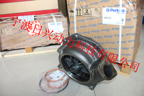
Coolant pump
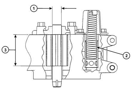
Shaft diameter at the position of the coolant seal (M) ... ... ... ... ... . 9,0 +/- 0,0 mm (0.7520 +/- 0.0004 in)
![]() 2
2
Recommended torque figures
Exceptions to these torque figures are given in the Workshop Manual where necessary.
Before any components are fitted to the engine, ensure that they are in a new or close to new condition. Bolts
or threads mus t not be worn or damaged. Components must be free from rust or other corrosion. Clean with
a non-corrosive cleaner if neces sary. Do not lubricate the threads of fasteners. Rust preventative which has
been applied by the component supplier for shipping and storage is acceptable. Certain components may
require an application of a particular lubricant, details are given in the Workshop Manual where relevant.
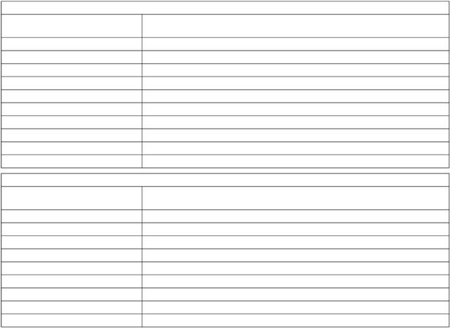
Standard torque figures for metric fasteners
Thread size
metric
M6
M8
M0
M2
M4
M6
M20
M24
M0
M6
Thread size
metric
M6
M8
M0
M2
M6
M20
M24
M0
M6
Metric nuts and bolts
Standard torque
2 +/- Nm (9 +/- 2 lbf ft)
28 +/- 7 Nm (2 +/- 5 lbf ft)
55 +/- 0 Nm (4 +/- 7 lbf ft)
00 +/- 20 Nm (75 +/- 5 lbf ft)
60 +/- 0 Nm (20 +/- 22 lbf ft)
240 +/- 40 Nm (75 +/- 0 lbf ft)
460 +/- 60 Nm (40 +/- 44 lbf ft)
800 +/- 00 Nm (590 +/- 75 lbf ft)
600 +/- 200 Nm (80 +/- 50 lbf ft)
2700 +/- 00 Nm (2000 +/- 220 lbf ft)
Metric taperlock studs
Standard torque
8 +/- Nm (6 +/- 2 lbf ft)
7 +/- 5 Nm ( +/- 4 lbf ft)
5 +/- 5 Nm (26 +/- 4 lbf ft)
65 +/- 0 Nm (48 +/- 7 lbf ft)
0 +/- 20 Nm (80 +/- 5 lbf ft)
70 +/- 0 Nm (25 +/- 22 lbf ft)
400 +/- 60 Nm (00 +/- 44 lbf ft)
750 +/- 80 Nm (550 +/- 60 lbf ft)
200 +/- 50 Nm (880 +/- 0 lbf ft)
![]() 2800
2800
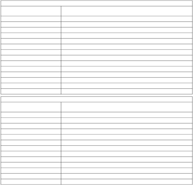
Standard torque figures for imperial fasteners
Thread size
inches
/4
5/6
/8
7/6
/2
9/6
5/8
/4
7/8
/8
/4
/8
/2
Thread size
inches
/4
5/6
/8
7/6
/2
5/8
/4
7/8
/8
/4
/8
/2
Imperial nuts and bolts
Standard torque
2 +/- Nm (9 +/- 2 lbf ft)
25 +/- 6 Nm (8 +/- 4 lbf ft)
47 +/- 9 Nm (5 +/- 7 lbf ft)
70 +/- 5 Nm (50 +/- lbf ft)
05 +/- 20 Nm (75 +/- 5 lbf ft)
60 +/- 0 Nm (20 +/- 22 lbf ft)
25 +/- 40 Nm (60 +/- 0 lbf ft)
70 +/- 50 Nm (275 +/- 7 lbf ft)
620 +/- 80 Nm (460 +/- 60 lbf ft)
900 +/- 00 Nm (660 +/- 75 lbf ft)
00 +/- 50 Nm (960 +/- 0 lbf ft)
800 +/- 200 Nm (20 +/- 50 lbf ft)
2400 +/- 00 Nm (780 +/- 220 lbf ft)
00 +/- 50 Nm (2280 +/- 260 lbf ft)
Imperial taperlock studs
Standard torque
8 +/- Nm (6 +/- 2 lbf ft)
7 +/- 5 Nm ( +/- 4 lbf ft)
5 +/- 5 Nm (26 +/- 4 lbf ft)
45 +/- 0 Nm ( +/- 7 lbf ft)
65 +/- 0 Nm (48 +/- 7 lbf ft)
0 +/- 20 Nm (80 +/- 5 lbf ft)
70 +/- 0 Nm (25 +/- 22 lbf ft)
260 +/- 40 Nm (90 +/- 0 lbf ft)
400 +/- 60 Nm (00 +/- 44 lbf ft)
525 +/- 60 Nm (90 +/- 44 lbf ft)
750 +/- 80 Nm (550 +/- 60 lbf ft)
950 +/- 25 Nm (700 +/- 90 lbf ft)
200 +/- 50 Nm (880 +/- 0 lbf ft)
![]() 2
2
Standard torque figures for ‘O’ ring face seal fittings and 7 degree flared fittings
|
Torque figures for ferrous straight thread ‘O’ ring fittings when connected to ferrous materials | ||
|
Outside diameter of nominal tube |
Thread size Inches |
Standard torque |
|
,8 mm (0.25 in) |
5/6 - 24 |
5,0 +/- ,5 Nm (4 +/- lbf ft) |
|
4,76 mm (0.88 in) |
/8 - 24 |
2 +/- 2 Nm (9 +/- lbf ft) |
|
6,5 mm (0.250 in) |
7/6 - 20 |
22 +/- 2 Nm (6 +/- lbf ft) |
|
7,94 mm (0.2 in) |
/2 - 20 |
0 +/- Nm (22 +/- 2 lbf ft) |
|
9,52 mm (0.75 in) |
9/6 - 8 |
48 +/- 5 Nm (5 +/- 4 lbf ft) |
|
2,70 mm (0.500 in) |
/4 - 6 |
82 +/- 8 Nm (60 +/- 6 lbf ft) |
|
5,88 mm (0.625 in) |
7/8 - 4 |
4 +/- 5 Nm (05 +/- lbf ft) |
|
9,05 mm (0.750 in) |
/6 - 2 |
90 +/- 20 Nm (40 +/- 5 lbf ft) |
|
22,22 mm (0.875 in) |
/6 - 2 |
250 +/- 25 Nm (85 +/- 8 lbf ft) |
|
25,40 mm (.000 in) |
5/6 - 2 |
00 +/- 0 Nm (220 +/- 22 lbf ft) |
|
,75 mm (.250 in) |
5/8 - 2 |
50 +/- 0 Nm (260 +/- 22 lbf ft) |
|
8,0 mm (.500 in) |
7/8 - 2 |
40 +/- 40 Nm (20 +/- 0 lbf ft) |
|
50,80 mm (2.000 in) |
2 /2 - 2 |
450 +/- 45 Nm (0 +/- lbf ft) |
Note: For the table above, use 50 percent of the torque figure when the fitting, the plug or the port material is
nonferrous.
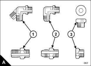
Examples of relevant fittings are shown (A): ‘O’ ring face s eal (A), 7 degree flare (A2) and plug with a
hexagon or socket-type head (A).
![]() 2800
2800
‘O’ ring face seal fittings
|
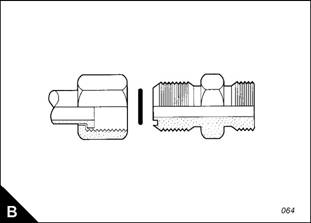
Torque figures for ferrous straight thread ‘O’ ring fittings (B) | |
|
Thread size inches |
Standards torque |
|
/4 |
8 +/- Nm (6 +/- 2 lbf ft) |
|
5/6 |
7 +/- 5 Nm ( +/- 4 lbf ft) |
|
/8 |
5 +/- 5 Nm (26 +/- 4 lbf ft) |
|
7/6 |
45 +/- 0 Nm ( +/- 7 lbf ft) |
|
/2 |
65 +/- 0 Nm (48 +/- 7 lbf ft) |
|
5/8 |
0 +/- 20 Nm (80 +/- 5 lbf ft) |
|
/4 |
70 +/- 0 Nm (25 +/- 22 lbf ft) |
|
7/8 |
260 +/- 40 Nm (90 +/- 0 lbf ft) |
|
400 +/- 60 Nm (00 +/- 44 lbf ft) | |
|
/8 |
525 +/- 60 Nm (90 +/- 44 lbf ft) |
|
/4 |
750 +/- 80 Nm (550 +/- 60 lbf ft) |
|
/8 |
950 +/- 25 Nm (700 +/- 90 lbf ft) |
|
/2 |
200 +/- 50 Nm (880 +/- 0 lbf ft) |
![]() 2
2
Torque figures for flared and ‘O’ ring fittings
The torque figures given in the table below and the table given on page 7 should be applied to the nut of the
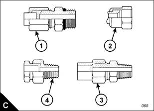
fittings whic h follow: 7 degree flared fittings (C), 45 degree flared fittings (C), inverted flared fittings (C2),
‘O’ ring fittings for a recessed drive, ‘O’ ring fittings for air conditioning and swivel nuts (C2). The figures should
be used for applications which allow these working pressures: 7750 to 4450 kPa (25 to 5000 lb/in²). The
torque figure depends on the size and type of fitting.
|
Nuts for 7 degree flared fittings | ||
|
Outside diameter of nominal tube |
Thread size Inches |
Standard torque |
|
,8 mm (0.25 in) |
5/6 |
5,0 +/- ,5 Nm (4 +/- lbf ft) |
|
4,76 mm (0.88 in) |
/8 |
+/- 2 Nm (8 +/- lbf ft) |
|
6,5 mm (0.250 in) |
7/6 |
6 +/- 4 Nm (2 +/- lbf ft) |
|
7,94 mm (0.2 in) |
/2 |
20 +/- 5 Nm (5 +/- 4 lbf ft) |
|
9,52 mm (0.75 in) |
9/6 |
25 +/- 5 Nm (8 +/- 4 lbf ft) |
|
9,52 mm (0.75 in) |
5/8 |
5 +/- 5 Nm (26 +/- 4 lbf ft) |
|
2,70 mm (0.500 in) |
/4 |
50 +/- 7 Nm (7 +/- 5 lbf ft) |
|
5,88 mm (0.625 in) |
7/8 |
65 +/- 7 Nm (48 +/- 5 lbf ft) |
|
9,05 mm (0.750 in) |
/6 |
00 +/- 0 Nm (75 +/- 7 lbf ft) |
|
22,22 mm (0.875 in) |
/6 |
20 +/- 0 Nm (90 +/- 7 lbf ft) |
|
25,40 mm (.000 in) |
5/6 |
5 +/- 5 Nm (00 +/- lbf ft) |
|
,75 mm (.250 in) |
5/8 |
80 +/- 5 Nm (5 +/- lbf ft) |
|
8,0 mm (.500 in) |
7/8 |
225 +/- 5 Nm (65 +/- lbf ft) |
|
50,80 mm (2.000 in) |
2 /2 |
20 +/- 0 Nm (240 +/- 22 lbf ft) |
Note: For the table above, use 50 percent of the torque figure when the fitting, the plug or the port material is
nonferrous.
| ||||||||||||||||||||||||||||||||||||||||
45 degree flared and 45 degree inverted flare fittings
|
45 degree flared and 45 degree inverted flare fittings | ||
|
Outside diameter of nominal tube |
Thread size Inches |
Standard torque |
|
,8 mm (0.25 in) |
5/6 |
5,0 +/- ,5 Nm (4 +/- lbf ft) |
|
4,76 mm (0.88 in) |
/8 |
8 +/- ,5 Nm (6 +/- lbf ft) |
|
6,5 mm (0.250 in) |
7/6 |
+/- 2 Nm (8 +/- lbf ft) |
|
7,94 mm (0.2 in) |
/2 |
7 +/- Nm ( +/- 2 lbf ft) |
|
9,52 mm (0.75 in) |
5/8 |
0 +/- Nm (22 +/- 2 lbf ft) |
|
, mm (0.48 in) |
/6 |
0 +/- Nm (22 +/- 2 lbf ft) |
|
2,70 mm (0.500 in) |
/4 |
8 +/- 4 Nm (28 +/- lbf ft) |
|
5,88 mm (0.625 in) |
7/8 |
50 +/- 5 Nm (7 +/- 4 lbf ft) |
|
9,05 mm (0.750 in) |
/6 |
90 +/- 8 Nm (65 +/- 6 lbf ft) |
|
22,22 mm (0.875 in) |
/4 |
00 +/- 0 Nm (75 +/- 7 lbf ft) |
Tapered pipe thread fittings
Thread size
Note: For the table above, use 50 percent of the torque figure when the fitting, the plug or the port material is
nonferrous.
![]() 2
2
Torque figures for standard hose clamps of the worm drive band type
|
Width of clamp |
Torque figure for initial installation on a new hose |
|
7,9 mm (0. in) |
0,9 +/- 0,2 Nm (8 +/- 2 lbf in) |
|
,5 mm (0.5 in) |
4,5 +/- 0,5 Nm (40 +/- 4 lbf in) |
|
5,9 mm (0.6 in) |
7,5 +/- 0,5 Nm (65 +/- 4 lbf in) |
|
Width of clamp |
Torque figure for used clamp |
|
7,9 mm (0. in) |
0,7 +/- 0,2 Nm (6 +/- 2 lbf in) |
|
,5 mm (0.5 in) |
,0 +/- 0,5 Nm (27 +/- 4 lbf in) |
|
5,9 mm (0.6 in) |
4,5 +/- 0,5 Nm (40 +/- 4 lbf in) |
Torque figures for const ant torque hose clamps
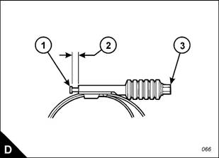
Use a torque wrenc h for the correct installation of a constant torque hose clamp. For a constant torque hose
clamp to be installed correctly, these conditions must exist:
The screw tip (D) must extend by 6,5 mm (0.250 in) beyond the housing (D2).
The belleville washers must be collapsed almost flat after the screw (D) has been tightened to a torque of
+/- Nm (98 +/- 9 lb in).
400-100-8969 15088860848
0574-26871589 15267810868
0574-26886646 15706865167
0574-26871569 18658287286


 English
 Espaol
 Franais
 阿拉伯
阿拉伯 中文(简)
中文(简) Deutsch
 Italiano
 Português
 日本
日本 韩国
韩国 български
 hrvatski
 esky
esky Dansk
Dansk Nederlands
 suomi
suomi Ελληνικ
 印度
印度 norsk
norsk Polski
 Roman
Roman русский
 Svenska