Perkins2806发动机喷油器电子喷射装置调整技术资料
Perkins2806发动机喷油器电子喷射装置调整技术资料
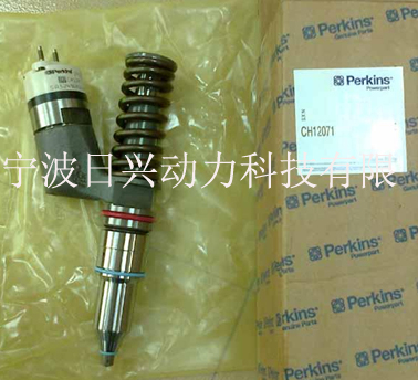

Electronic injector units
To remove and to fit
Special requirements
Operation -2
To remove
Brush
Warning! The electrical circuit for the fuel injector units operates on 0 volts. Do NOT work on the fuel injector
units unless the power supply to the ECM has been disconnected.
Remove the relevant rocker shaft assembly, Operation -2.
2 Loosen the two nuts and remove the electrical connector from the injector unit.
Mark the valve bridge pieces to assist during assembly, then remove them.
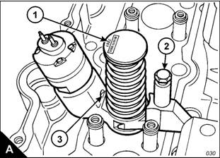
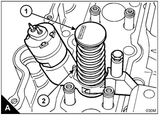
4 Remove the bolt (A2) from the spacer and clamp which retain the injector unit and use the special tool,
GE5002, to release the injector unit from the cylinder head.
Caution: If more than one injector unit is to be removed, make a note of the trim code (A), a four-digit number
adjacent to the bar code, and also the cylinder to which the unit is fitted.
5 Remove the injector unit, together with the spacer and clamp.
6 Use the vacuum pump, GE50028, together with the tube, GE5000, and bottle, GE50029, to ex tract any
fuel which has spilled into the combustion chamber during removal of the injector.
![]()
To fit
Clean thoroughly the bore of the injector sleeve and cylinder head. Use the special brushes (GE50022,
GE5002 and GE50024) to remove carbon or dirt.
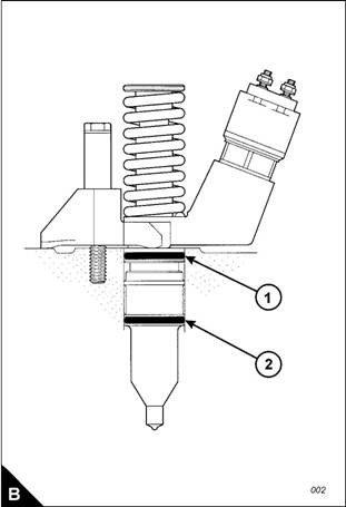
2 Check the condition of the ‘O’ ring seals (B and B2); renew the seals if they are worn or damaged. Lubricate
the ‘O’ ring seals with clean engine oil before the injector unit is installed in the cylinder head.
Caution: Injector units MUST be fitted to their original positions or the information in the ECM will need to be
updated.
Fit the injector unit to the cylinder head. Fit the clamp, spacer and retaining bolt. Tighten the bolt (A2) to a
torque of 47 +/- 9 Nm (5 +/- 7 lbf ft).
4 Fit the bridge pieces.
5 Attach the electrical connector to the injector unit and retain with the two nuts. Tighten the nuts to a torque
of 2,5 Nm (22 lbf in).
6 Fit the rocker shaft assembly, Operation -2.
 2800
2800
To check and to adjust
Special requirements
Operation -
|
Special tools | |
|
Description |
Part number |
|
Injector height gauge |
CH49 |
This operation should be performed at the same time as the operation to check the valve tappet c learances.
Warning! The electrical circuit for the fuel injector units operates on 0 volts. Do NOT work on the fuel injector
units unless the power supply to the ECM has been disconnected.
With the rocker covers removed, set the number piston to TDC (top dead centre) on its compression
stroke. Check/adjust the height dimensions for the fuel injectors of cylinders , 5 and 6.
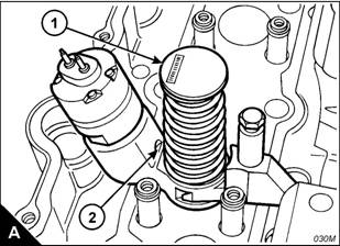
2 Use the fuel injector setting gauge, CH49, to obtain the correct height for the fuel injector. The dimension
to be measured is from the top of the unit injector (A) to the machined ledge on the fuel injector body (A2).
This dimension should be 78,0 +/- 0,2 mm (.07 +/- 0.0 in). Slacken the lock nut and use the adjus tment screw
of the rocker lever to obtain the correct dimension. Tighten the lock nut to a torque of 55 +/- 0 Nm (4 +/-
7 lbf ft).
Remove the timing bolt from the flywheel housing and rotate the flywheel by 60 degrees in the normal
direction of engine rotation until the timing bolt can be inserted into the threaded hole. This will put the number
piston at TDC in its exhaust stroke.
4 Check/adjust the height dimensions for the fuel injectors of cylinders , 2 and 4 as given in step 2.
When all adjustments have been made, remove the timing bolt, fit the cover to the flywheel housing, fit the plug
to the timing bolt position and fit the rock er covers.
帕金斯柴滤,帕金斯2645a747喷油器,包头珀金斯配件那有,珀金斯配件那有,帕金斯增压器多少钱,帕金斯发动机四缸的机滤,帕金斯分配泵,沃尔沃940配件,tad1232ge水泵,tad1232ge水泵价位,沃尔沃柴油发电机皮带型号,沃尔沃柴油机四配套多少钱,twd 1240 ve 水泵,沃尔沃1241起动机价格,沃尔沃柴油机大修理包哪有卖
400-100-8969 15088860848
0574-26871589 15267810868
0574-26886646 15706865167
0574-26871569 18658287286


 English
 Espaol
 Franais
 阿拉伯
阿拉伯 中文(简)
中文(简) Deutsch
 Italiano
 Português
 日本
日本 韩国
韩国 български
 hrvatski
 esky
esky Dansk
Dansk Nederlands
 suomi
suomi Ελληνικ
 印度
印度 norsk
norsk Polski
 Roman
Roman русский
 Svenska