 English
 Espaol
 Franais
 阿拉伯
阿拉伯 中文(简)
中文(简) Deutsch
 Italiano
 Português
 日本
日本 韩国
韩国 български
 hrvatski
 esky
esky Dansk
Dansk Nederlands
 suomi
suomi Ελληνικ
 印度
印度 norsk
norsk Polski
 Roman
Roman русский
 Svenska
2806Perkins柴油发电机组缸套维修安装测量方法
2806Perkins柴油发电机组缸套维修安装测量方法
Cylinder liners
To remove and to fit
Special requirements
Operation 7-2
|
Special tools |
Consumable products | ||
|
Description |
Part number |
Description |
Part number |
|
Cylinder liner remover |
GE5000 |
Anti-seize compound |
CV60890 |
|
Cylinder liner instal ler |
GE50000 |
Anti-seize compound |
CV60890 |
To remove
Remove the pistons and connecting rod assemblies, Operation 4-.
2 Fit c overs over the journals of the crankshaft for protection from dirt or water.
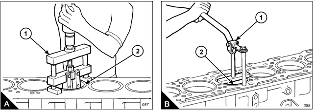
Use the special tool (A), GE5000, to remove the cylinder liners (A2). Make a note of the bore position to
which each liner is fitted.
To fit
Clean the cylinder liners and the liner bores in the crankcase.
2 Install the cylinder liners in the cylinder block without the ‘O’ ring seals or the filler band. Ensure that the
cylinder liners are fitted to their original pos itions.
Check the protrusion of the cylinder liners, Operation 7-.
4 Remove the liners and fit new ‘O’ ring seals.
Note: Apply liquid soap and/or clean engine oil immediately before assembly. Do not apply the liquid soap and/
or clean engine oil to the seals too early as the seals may swell and become pinched by the liners during
installation.
5 When the engine is ready for final assembly, the ‘O’ ring seals, the cylinder block and the upper filler band
must be lubricated before installation. If the lower ‘O’ ring seals are black in colour, apply liquid soap to them
and to the cylinder block, and immerse the upper filler band in clean engine oil. If the lower ‘O’ rings are brown
in colour, apply engine oil to them, to the cylinder block and immerse the upper filler band in clean engine oil.
6 After the engine oil or liquid soap has been applied, immerse the filler band in clean engine oil, then
immediately fit the filler band to the groove in the cylinder liner below the liner flange. Immediately install the
cylinder liner in the crankcase before expansion of the band occurs. Use the special tool (B), GE50000, to
install the liners (B2). Ensure that the liners are fitted to the correct positions.
7 Fit the pistons and connecting rod assemblies, Operation 4-.

![]()
![]() 7
7
2800
To check and to adjust the protrusion of the cylinder liners
Special requirements
Operation 7-
|
Special tools | |||
|
Description |
Part number |
Description |
Part number |
|
Clamp bolt |
GE50005 |
Fibre washer |
GE50007 |
|
Clamp washer |
GE50006 |
Cylinder liner projection tool |
GE50002 |
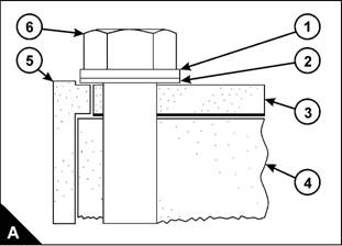
Note: Cylinder liner protrusion is measured from the top of the cy linder liner to the top of the spacer plate.
Ensure that the top face of the cylinder block (A4) is clean. Fit a new spac er plate gasket and fit a clean
spacer plate (A).
2 Fit the cy linder liners to the cylinder block without seals or bands. Ensure that the cylinder liners are fitted
to their original positions.
Install all of the bolts (A6), GE50005, or the six bolts around the liner (A5) to be checked. A plain washer
(A), GE50006, and a fabric washer (A2), GE50007, must be fitted to each bolt. Tighten the bolts to a torque
of 95 Nm (70 lbf ft).
4 Use the special tool, GE50002, to measure the liner protrusion at the four positions shown (B, B2, B and
B4) and record the measurements for each cylinder.
5 Add the four readings for each cylinder and divide the sum of the readings by four to obtain the average
reading for eac h cylinder.
The correct specifications for cylinder liner protrusion are:
Liner protrusion: 0,025 to 0,52 mm (0.00 to 0.006 in)
Maximum variation in each liner: 0,05 mm (0.0020 in)
Maximum average variation between adjacent liners: 0,05 mm (0.0020 in)
Maximum variation between all liners: 0,02 mm (0.0040 in)
Note: If the liner protrusion changes around the liner, turn the liner to a new position within the bore. If the liner
protrusion is not within the specifications, move the liner to a different bore. Inspect the top face of the cylinder
block.
Continued7
6 If the liner protrusions are all below the specifications or low in the range, 0,025 mm (0.00 in) or 0,05 mm
(0.002 in), try a thinner spacer plate, available from your Perkins dealer. These plates are 0,076 mm (0.00 in)
thinner than the original plate and will increase the liner protrusion. Use these spacer plates to compensate for
low liner protrusions whic h are less than the 0,076 mm (0.00 in). Use these spacer plates if inspec tion of the
top face of the cylinder block reveals no measurable damage directly under the liner flanges but the average
liner protrusion is less than 0,076 mm (0.00 in).
Caution: Do not exceed the maximum liner protrusion of 0,52 mm (0.006 in). Excessive liner protrusion will
cause the liner flange to crack.
7 When the liner protrusion is correct, add a temporary mark to the liner and to the spacer plate to assist with
the assembly procedure. Remove the bolts and washers, and withdraw the cylinder liners.
8 When the engine is ready for final assembly, the ‘O’ ring seals, the cylinder block and the upper filler band
must be lubricated before installation. If the lower ‘O’ ring seals are black in colour, apply liquid soap to them
and to the cylinder block. Immerse the upper filler band in clean engine oil. If the lower ‘O’ rings are brown in
colour, apply engine oil to them and to the cylinder block. Immerse the upper filler band in clean engine oil.
Note: Apply liquid soap and/or clean engine oil immediately before assembly. Do not apply the liquid soap and/
or clean engine oil to the seals too early as the seals may swell and become pinched by the liners during
installation..珀金斯发动机配件,帕金斯发动机机体,帕金斯1103a 33tg2缸盖,三菱柴油发电机组配件,东北珀金斯发动机配件,康明斯QSX15柴油发动机ECM,帕金斯u5lt0317缸垫,三菱柴油发电机配件,拉萨帕金斯发动机配件,珀金斯4012威尔信配件,威尔信P2000E 大修备件
400-100-8969 15088860848
0574-26871589 15267810868
0574-26886646 15706865167
0574-26871569 18658287286
