康明斯电喷柴油发动机电路图的使用
Cummings EFI diesel engine circuit diagram of the use of
电路图是电控系统故障排查中必不可少的资料。能快速正确地阅读康明斯电路图是电控系统故障判断的前提之一。康明斯电路图是介于电路原理图和电路装配图之间的一种电路图。装配图能详细反映电路的走向和零部件及插头的形状,如下左图所示;原理图则只是反映电路的工作原理,非常简化。康明斯电路图吸收两种电路图的优点,非常易于阅读。
装配图原理图
Circuit diagram is electrically controlled system troubleshooting essential information. Can quickly and correctly reading Cummins circuit diagram is one of premise of electronic control system fault diagnosis. Cummins circuit is a circuit diagram and circuit assembly between a circuit diagram. Assembly drawing can reflect the trend and the detailed circuit components and plug shape, as shown on the left; schematic just reflect the electric circuit principle of work, very simplified. Cummins circuit diagram is absorbed by the two circuit figure of merit, very easy to read.
Assembly diagram

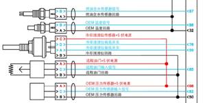
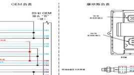
康明斯电路图示例
Cummins circuit diagram
电路图中的颜色
康明斯原装的电路图为彩色图,图中的线路总共有五种颜色,分别是红色、蓝色、黑色、紫色和绿色。红色代表系统供电电路的火线,包括电瓶向 ECM 的供电电路火线和 ECM向输入输出设备供电电路的火线;蓝色代表输入设备向 ECM输入信号的信号电路,包括各种开关和传感器及油门的输出信号线;黑色代表供电电
路的地线,包括电瓶回路的地线和 ECM向输入输出设备供电的地线;紫色代表 ECM向输出设备提供控制信号的控制信号线;绿色为数据通信线路。康明斯电喷柴油发动机电路图|康明斯电喷柴油发动机维修技术|康明斯电喷柴油发动机电路图资料|康明斯电喷柴油发动机维修服务商
电路中的符号
电瓶
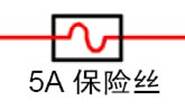
保险丝
Circuit diagram of the color
Cummings original circuit for color map, map of the line has a total of five colors, red, blue, black, and green, purple. Red represents power supply circuit line, including the battery to the ECM line and ECM power supply circuit to the input / output device power supply circuit wire; blue representing the input device to the ECM input signal circuit, including a variety of switches and sensors and the output signal line; black represents power supply
Road ground, including battery circuit ground and ECM to input and output equipment power supply wire; the purple represents ECM to output device provides a control signal to the control signal line; green for data communication line.
Circuit symbols
Storage battery
Fuse

ECM上的插头示例
钥匙开关
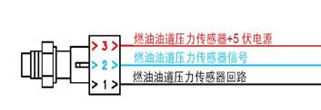
传感器示例
电子油门

开关
电路图的结构
康明斯提供的发动机安装到主机厂设备上,需要主机厂完成一系列的接线,其中包括 ECM的供电电路、发动机的启动电路、油门电路、指示灯和控制开关电路等等。在康明斯电路图中通过一根虚线将整个电路图一分为二,图中标明左边电路为 OEM(主机厂)负责,右边电路为康明斯负责,即左边电路由主机厂负责安装,右边电路为发动机的出厂状态。
需要指出的是,在实际的设备中,主机厂的电路连接不会完全和康明斯原装电路图中的接法一样。这是因为康明斯电路图中推荐的接法包含了发动机所有的特性,而主机厂在安装时有些控制功能可能不启用,或者在康明斯允许的前提下对电路作一定的改动。
Switch
Circuit diagram of structure
Cummings provided the engine mounted to the host plant, requiring a host plant to complete a series connection, which includes a ECM power supply circuit, the engine starting circuit, a throttle circuit, indicating lamp and a control switch circuit and so on. In the Cummings circuit by a dotted line to the entire circuit diagram of one divides into two., indicating the left circuit for OEM ( OEM ) is responsible for, the circuitry responsible for Cummings, which left circuit by the host plant is responsible for the installation, the circuit for engine state.
It is noted that, in the actual equipment, host plant circuit connection does not completely and Cummings original circuit diagram of the connection. This is because the Cummins circuit diagram of the recommended connection contains all engine characteristics, while the host plant in the installation of some control functions may not be enabled, or in Cummins allowed under the premise of circuit must change.
ECM供电电路
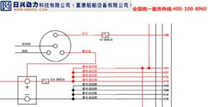
如前所述 ECM本身是需要外部供电的,如果 ECM的供电电路有问题,可能导致整个系统不能工作。对康明斯车用和工程机械用电控发动机,ECM的供电电路包括无开关电源和开关电源两部分,如下图所示。
无开关电源通过电瓶直接向 ECM供电,除了保险丝以外,不允许再接其它的元件。在 CM850/870/875之前的 ECM,无开关电源通常由三组(火线和地线)以上的线路构成,这是因为 ECM的工作电流较大,通过一组导线不能提供足够的工作电流。对 CM850/870/875,ECM的无开关电源通过一个专用的插头导入。
开关电源是通过钥匙开关后接入 ECM的一根火线,接入 ECM前通常还有一个保险丝。在钥匙开关处在 OFF关位置时,此火线处在断开的位置。 ECM通过此处的电压信号判断开始或者结束工作,通常这里的信号也是发动机的熄火信号。
需要指出的是,对康明斯 G-drive机组驱动用发动机, ECM的供电电路中没有开关电源,而只有无开关电源。
ECM power supply circuit
As the ECM itself is the need for external power supply, if the ECM power supply circuit has a problem, may cause the whole system can not work. The Cummings car and engineering machinery engine, ECM power supply circuit comprises a switch power supply and switch power supply part two, as shown below.
No switching power supply through the battery directly to the ECM power supply, in addition to fuse, not permitted to be connected with other components. Before the CM850/870/875ECM, no switching power supply is usually composed of three groups ( live line and ground line ) above the line, this is because the ECM working current is large, by a group of wires do not provide adequate working current. On CM850/870/875, ECM without switching power supply through a dedicated plug into.
Switching power supply is the key switch access ECM after a battle line, access to ECM before there is usually a fuse. Key switch is in the off position in OFF, this line is in the disconnected position. ECM through the voltage signal to judge the beginning or the end of the work, there is usually also the engine flameout signal signal.
What need points out is, to Kang Mingsi G-drive set driving engine, ECM power supply circuit without switch power supply, but no switching power supply.
钥匙开关与起动电路
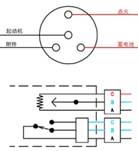
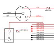
钥匙开关是绝大部分汽车和工程机械上的一个标准元件,用于控制整车的运行。钥匙开关的背面有四个接线柱,如右图所示分别为电瓶、附件、起动机和点火。钥匙开关的正面,即司机的操作,也有四个位置,分别为 ACC, OFF, ON和 ST,所以钥匙开关也俗称四位置开关。
钥匙开关通过背面的电瓶接线柱接受来自电瓶的火线,然后通过钥匙的不同位置,向不同的元件提供电源。由于系统采用负极搭铁,钥匙开关上没有地线,只有火线。
一般来说,下表列出了钥匙开关处在四个不同位置时,钥匙开关背面四个极柱的供电状态。假设系统使用 24伏电压。
Key switch and starting circuit
Key switch is the vast majority of automobile and engineering machinery on a standard element, used to control the vehicle running. Key switch back has four terminals, such as shown in the figure are batteries, accessories, starter and ignition. Key switch front, namely the driver's operation, also has four positions, respectively ACC, OFF, ON and ST, so the key switch is also commonly known as the four position switch.
Key switch through the back side of the battery terminal post to accept from battery battle line, and then through the keys to different positions, different elements to provide a power source. Because the system uses the negative electrode, the key switch without ground, only line.
In general, the following table lists the key switch in four different positions, the key switch backside four poles and the power supply state. If the system uses 24 volt voltage.
1.
 4. 电瓶极柱 5. 柱附件极6. 柱点火极7. 柱起动极
位置
8. ACC 9. 24伏 10. 24伏 11. 0伏 12. 0伏
13. OFF 14. 24伏 15. 0伏 16. 0伏 17. 0伏
18. ON 19. 24伏 20. 24伏 21. 24伏 22. 0伏
23. ST 24. 24伏 25. 0伏 26. 24伏 27. 24伏
起动电路用于控制发动机的起动和熄火,是发动机控制系统的基本部分。绝大部分汽车用和工程机械用发动机的起动电路都是基本一样的。参与起动控制的基本元件都包括钥匙开关和一个起动继电器,钥匙开关控制起动继电器,起动继电器控制起动马达。上图给出了一个起动电路的示
Starting circuit for controlling the engine starting and extinguishing, is a basic part of engine control system. The vast majority of automobile and engineering machinery engine starting circuit are basically the same. Involved in starting control basic element includes a key switch and a starting relay, a key switch control starting relay, starter relay to control the starting motor. This gives a starting circuit indicator
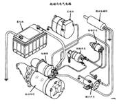
例,用于康明斯机械控制发动机的起动马达控制。不同的厂家设计的起动电路可能会略有不同,但其基本的控
制原理都如下图所示。不同的厂家在设计起动电路时,可能会在钥匙开关和起动继电器之间的控制线上增加一
些辅助的控制电路。如上所述,对车用和工程机械用发动机,如果是电控发动机, ECM并不参与起动控制,整个起动电路是
独立的。而对康明斯发电机驱动用电控发动机(G-Drive),ECM则参与起动电路的控制,如下图所示 QSX15
(发电机驱动用)的起动电路。
For example, Cummins machine control engine starting motor control. Different manufacturers to design starting circuit may be slightly different, but the basic control
Its principle is as shown below. Different manufacturers to design starting circuit, may be a key switch and starter relay between the control line to increase a
Some auxiliary control circuit. As mentioned above, the vehicle and engineering machinery engine, if the engine, ECM is not involved in starting control, the starting circuit is
Independent. The Cummings generator driven by engine ( G-Drive ), ECM is involved in the control of starting circuit, as shown in figure QSX15
( the generator driven by the starting circuit ).
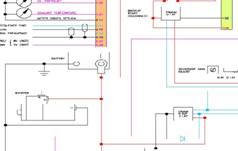
在下列电路图中,二个起动继电器控制起动马达的工作,系统不再有钥匙开关。 ECM通过控制第一个起动继电器控制电路的地线来控制马达的起动。在所有预设的条件都达到的前提下,ECM给出第一个起动继电器的控制地线,触发整个起动电路。
In the following diagram, two starting relay to control the starting motor work, there is no longer a key switch system. The ECM by controlling the first starting relay control circuit earth wire to control the starting of the motor. In all the preset conditions are achieved under the premise, ECM gives the first starting relay control wire, triggering the start circuit.
400-100-8969 15088860848
0574-26871589 15267810868
0574-26886646 15706865167
0574-26871569 18658287286


 English
 Espaol
 Franais
 阿拉伯
阿拉伯 中文(简)
中文(简) Deutsch
 Italiano
 Português
 日本
日本 韩国
韩国 български
 hrvatski
 esky
esky Dansk
Dansk Nederlands
 suomi
suomi Ελληνικ
 印度
印度 norsk
norsk Polski
 Roman
Roman русский
 Svenska