 English
 Espaol
 Franais
 阿拉伯
阿拉伯 中文(简)
中文(简) Deutsch
 Italiano
 Português
 日本
日本 韩国
韩国 български
 hrvatski
 esky
esky Dansk
Dansk Nederlands
 suomi
suomi Ελληνικ
 印度
印度 norsk
norsk Polski
 Roman
Roman русский
 Svenska
COMMINS QSX15 QSK23 QSK45 QSK60 QSK78发动机ECM技术使用手册
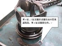
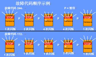
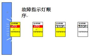
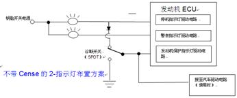
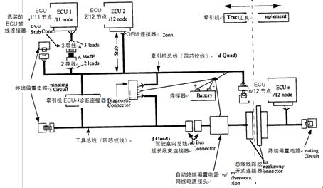
进口发动机QSX15执行器故障容易导致缸盖活塞开裂 美国康明斯进口发动机QSX15为工业用全电控发动机,性能优良,节能效果明显;但使用中一定要注意保证燃油质量,注意观察发动机烟色,听发动机异常声响;应为采取的燃油执行器和正时执行器是提供燃油的关键部件,出现磨损等故障不易检查和发觉,没有直接故障代码指示,往往是造成恶性故障而容易忽视的环节。 COMMINS-QSX15 QSK23 QSK45 QSK60 QSK78系列发动机ECM技术使用手册 cummins 柴油机配件 ecm是柴油机的哪部分 qsx15康明斯发动机的怎样用电脑软件查看故障历史 电喷发动机踩下油门就熄火 电喷的发电机是什么 原理 康明斯ISLe维修手册 康明斯ISE油泵 那个公司有康明斯发动机上的油压传感器 康明斯热交换器芯及热交换器总成 康明斯发动机水温感应塞 康明斯发动机零件号 康明斯 调速器过热 执行器发卡 康明斯发动机水泵讲解 康明斯 轨压传感器 东风汽车康明斯电喷系统图 第I节 - Quantum诊断 ***的诊断技术 ***的诊断技术可对Quantum发动机进行简单的维修和服务。故障或保养条件的诊断检验可通过机载或非机载系统进行。 机载诊断 ECM具有大范围检测故障的能力 闪烁故障代码 位于驾驶室仪表盘上的故障指示灯可指示警告/停机故障 保养指示灯 机载诊断 故障检测 在设备自己工作期间,当钥匙开关处于ON位置时检测故障。如果此时故障变为现行故障(当前检测到),存储器中就会记录故障,同时记录发动机参数速录数据。另外根据现行故障的严重程度,特定的故障可能会使警告指示灯(黄色)或停机指示灯(红色)、保养指示灯或燃油含水(WIF)指示灯变亮。 闪烁故障代码 可通过诊断开关或油门踏板进入故障代码闪烁模式。要进入故障代码闪烁模式,钥匙开关必须处于ON(接通)位置并且发动机停机。使用诊断开关进入该模式时,在诊断开关转到ON位置后,ECM将自动闪烁第一个故障代码。诊断增加/减少将向前或向后调整现行故障代码。要使用油门踏板进入故障代码闪烁模式,必须循环踩下和释放油门踏板,使油门开度连续3次从0到100%。一旦进入诊断模式,循环踩下和释放油门踏板可顺序向前达到现行故障代码。下图描述了通过停机指示灯指示的故障代码闪烁方式的类型。 故障指示灯 Quantum系统使用多达5个指示灯(每个指示灯具有两种功能):停机指示灯、警告指示灯、保养指示灯/发动机保护指示灯(所有发动机系列使用其中一个,而不是同时使用两个)、等待起动指示灯和燃油含水指示灯。如果钥匙开关转到ON位置而诊断开关保持断开,这些指示灯将会亮约2秒钟然后熄灭,以证实指示灯正常工作和接线正确。参阅下面的插图,这些指示灯全部变亮然后每次熄灭一个。 警告指示灯 – 用于所有Quantum发动机 - 警告指示灯提供重要的操作员信息。要求操作员及时注意这些信息。 警告指示灯还用于描述诊断故障代码。 停机指示灯 – 用于所有Quantum发动机 - 停机指示灯提供紧急的操作员信息。这些信息要求操作者快速响应并采取正确措施。停机指示灯还用于闪烁诊断故障代码。 发动机保护指示灯 – 用于QSK19/45/60, QST30发动机 - 当存在发动机保护故障时,发动机保护指示灯将变亮。可通过OEM配线配置系统,以便用红色/停机指示灯指示发动机保护故障。这是通过将红色指示灯连接至ECM的红色/停机指示灯输入和发动机保护指示灯输入来实现的。如果发动机保护指示灯信号用于控制其它功能,如车辆驱动电路,该电路中必须接入一个二极管。 选装 - 2指示灯布置方案- 用于QSK19/45/60发动机 - 选装的2-灯布置方案将取消发动机保护(白色)指示灯。因此,操作员仪表盘上只有一个警告指示灯(黄色)和一个停机指示灯(红色)。所有通过发动机保护指示灯指示的故障将通过停机(红色)指示灯来指示。这种改进只会影响故障指示灯的线路布置,不会影响软件或标定程序。参阅下面的线路图。 第II节 - ECM串行通信 Quantum串行通信 本文件的目的是提供设备与Quantum控制器串行通信接口应用类型有关的信息。本文件的内容分为两大类。 第一类适用于制造设备的OEM,因此对他们来讲,数据通信接口的安装是关心的问题。此类内容提供了电缆、连接器信息以及列出了经过康明斯测试与Quantum控制器兼容的数据通信装置。第二类收集了OEM和设计与Quantum控制器相连的数据通信接口的部件供应商使用的信息。这类信息详细描述了与信息支持、参数特征、网络应用和诊断有关的内容。 导言 数据通信接口使得设备上的电子装置彼此相互连接。有些典型功能共享传感器数据,共享计算信息,允许子系统(如发动机、变速箱等)之间的工作相互影响,子系统工作状态通信。数据通信接口还可提供机载或非机载诊断工作模式。 Quantum控制器具有两个独立的串行通信端口。一个端口用于访问SAE J1939并与J1939-11兼容,另一个端口用于SAE J1587并与J1708兼容。Quantum控制器不支持SAE J1922。 SAE J1939数据通信装置是一种高速网络,用于在250K 波特下工作的设备。它能够支持控制、信息共享、诊断、多路传输和专有通信。J1939(物理层)数据通信采用微分线路驱动器电路,允许最长的总线长度为40米。在给定的时间内,网络最多可提供30个节点连接。 SAE J1587是在9600波特的速度下工作的J1708基线网络。它支持信息共享、诊断和专有通信。在给定的时间内,网络最多可提供20个节点连接。 当设备钥匙开关转到ON(接通)位置时,Quantum控制器上的J1939/J1587数据通信接口同时起作用。 适用的SAE文件 本文件与下面列出的SAE技术规范含有提供Quantum通信接口(J1939和J1587)与设备应用类型相连的信息。 SAE 1939 推荐用于串行控制和通信网络的常例(1997年4月)。它提供一个计划的J1939-xx文件列表,还提供有关网络的全套文件和基本操作的简单指导。 SAE J1939-11 物理层(1997年3月)。在250Kb/秒的速度下工作,线性总线带有屏蔽双绞线回路。 SAE J1939-12 物理层(工作草案为ISO 11783 中的第2部分,1997年5月)。在250Kb/秒的速度下工作,线性总线带有四芯绞线。 SAE J1939-13 非机载诊断连接器(1997年1月),指定9-针Deutsch连接器为J1939, J1587和二级CAN网络提供工具、无开关电源和接地连接。 SAE J1939-21 数据通信层(1998年7月),指定CAN 2.0b作为使用的信息协议,同时还定义了J1939应用层的接口。 SAE J1939-71 车辆应用层(1996年5月和97年1月的附录),定义了传输参数值解释规则,允许接收装置确定发送装置能否提供与参数据组有关的所有参数,任何参数是否存在错误状态,或信号是否有效。 SAE J1939-73 诊断应用层(1998年10月)- 诊断。定义在J1939布置方案上执行诊断需要的容量,以确定发生故障的子系统最少可维修的特性,如何发生故障,读取和清除诊断故障代码,诊断指示灯状态的通信,以及提供维修工具监测的多种参数。 SAE J1939-81 网络管理 (1996年11月) SAE J1587 (1996年3月和97年1月的附录) - 重型设备应用类型微机系统之间的连接SAE/TMC电子数据交换。定义信息和数据的格式以及用于传输频率和环境信息的指导方针。 SAE J1708 物理层(1993年10月)- 重型设备应用类型微机系统之间的串行数据通信。 适用的康明斯文件 可在下列康明斯技术标准和文件中找到数据通信接口的其他信息: 接口技术规范:1377-9804 - 输入和输出的J1939多路传输。为通过J1939数据通信接口而不是通过分离的导线(巡航控制开关输入,指示灯输出等)提供给发动机或由发动机提供的信息提供信号处理要求。 AEB 15.44 Quantum安装建议文件 J1939安装信息 本节提供了在设备上安装J1939数据通信接口需要的信息。请参考AEB 15.44 - Quantum安装建议中的详细信息。 用于QSM11和QSX15的强制性EA(数据通信接口)选装件 不适用于QSK 19 J1939 为在发动机上安装J1939数据通信接口,理解电缆布线和连接器的要求是很重要的。下一节提供了电缆布线和连接器的详细信息。还提供了某些供应商的信息,以便采购电缆和连接器。 3. 电缆布线 主干线束 - 一种最大长度为40米(约131英尺)的线性总线。在给定的时间内可连接至主干网的最大节点数(电子控制器)为30。注意,B和B MATE(配合件)(2按键型)是主干线束和终端连接器按键,B为插座,B MATE为插头。 为了与J1939-11一致,主干线束为带加蔽线的屏蔽双绞线,并在每个网络终端都需要被动终端电阻。J1939-11布局典型用于汽车/公路应用类型。请参考图1。 为了与J1939-12一致,主干线束是带加蔽线的四芯绞线,并在网络的每端都需要主动终端和偏置电路。物理层使得J1939-11无须屏蔽。物理层还采用收发机电路设计,允许J1939-11节点在同一网络中作为J1939-12节点存在。 短线 - 主干线束与每个节点(电子控制器)的连接称为短线,最长为1米(约3.3英尺)。请参考图1。 屏蔽 - 电气连接的屏蔽是通过节点(电子控制器)的总线连接点和主总线的内部连线处的加蔽线来实现的。还应注意屏蔽只能在蓄电池负极的一处接地。尽管屏蔽不能覆盖线性总线或短线连接器(阅读下节中的详细信息)的连接部位,它仍与下段屏蔽电缆建立电气连接,并提供充分的覆盖,以提供必要的电磁兼容性(EMC)。 连接 发动机连接 - Quantum控制器可通过称为短线连接器的3-针未屏蔽连接器与主干线束相连。这在图1中ECU1连接到主干线束的方法中表示出来。图1中还表示出短线连接器有一个特殊键(1类键),在图中表示为A和A MATE,其中A MATE 是另一半配合件。对于图1中有关ECU 1所示的连接类型,三根触针中的一根将用来穿过短线连接器的配合件(A MATE)与加蔽线相连,以便保持屏蔽的电气导通性。另外两个SAE J1939支持的连接电子控制器与主干线束的触针在图X中显示出来。应当注意,ECU 2的连接提供最佳的外壳EMC改进(例如最短的短线)。 注:制作主干线束时,OEM必须提供发动机J1939维修接头。 诊断连接 - 诊断连接器是9针Deutsch连接器,为J1939、二级CAN网络提供工具(用于农业/工程机械应用类型)、无开关电源和接地连接。来自主干线束的诊断连接器允许的最大距离为2/3米(0.67米)。诊断连接器与连接诊断连接器的工具接口电路之间最大允许的距离为另外的1/3米(0.33米)。 对于汽车/卡车工业,SAE推荐的连接器位置处于驾驶室中的操作员侧,并在操作员侧接地。对于J1587的6-针连接器安装,推荐使用Deutsch HD10-6-12P连接器。对于J1939和J1587的9-针连接器安装,建议使用Deutsch HD10-9-1939P连接器 - 请参考AEB 15.10的4.0节中更为详细的信息。 穿墙式连接器(Bulkhead Connection) - J1939数据通信接口可穿过OEM穿墙式连接器。为降低电噪声对数据通信接口的影响,建议不要把导线置于具有极高电流负荷或开关电流的电路附近。建议安装者在所有继电器上设计回程二极管,防止出现系统噪音问题。 5. J1939电缆和连接器供应商 J1939兼容连接器和电缆现在由许多本地和本国经销商提供。 British perkins commonly used models and prices perkins power 500 kw diesel generator will letter generator producing area Import engine QSX15 easily result in the crack of the cylinder piston actuator malfunction The United States imported cummins engine QSX15 for industrial use full electronic control engine, high performance, energy-saving effect is obvious; But must pay attention to ensure the quality of fuel oil in use, observe the engine smoked, listening to the engine abnormal sound; Should take the fuel actuator and timing actuators are key components in fuel, such as wear fault is not easy to check and find, no direct fault code instructions, are often caused by malignant fault and easy to ignore the link. COMMINS - QSX15 QSK23 QSK45 QSK60 QSK78 series engine ECM technical manual Cummins diesel engine accessories The ecm is which part of the diesel engine Qsx15 cummins engine how to use computer software to check the fault history Efi engine hit the throttle will stall efi generator is what principle Cummins ISLe maintenance manuals Cummins ISE oil pump The company has a cummins engine oil pressure sensor Cummins and heat exchanger heat exchanger core assembly Cummins engine water temperature induction plug Cummins engine part number Cummins governor actuator hairpin overheat Cummins engine water pump Cummins rail pressure sensor Dongfeng cummins efi system diagram The first section I - Quantum diagnosis The diagnosis of advanced technology Advanced diagnostic technology for Quantum engine for simple maintenance and service. The diagnostic test condition of failure or maintenance may be done by airborne or airborne systems. On-board diagnosis The ECM has a wide range of detection fault Scintillation fault code Located in the cab can be indicates a warning/fault indicator light on the dashboard outage Maintenance indicator On-board diagnosis Fault detection During his work, when the key switch in the ON position detection fault. If the failure into the current failure detected (current), will record the fault memory, at the same time record the engine parameters SuLu data. Additionally according to the severity of the fault current, a specific failure could cause the warning light (yellow) or stop the indicator light (red), maintenance indicator or fuel oil water cut (WIF) light is brighter. Scintillation fault code Through diagnosis into fault code flashing mode switch or the accelerator pedal. To enter the flashing mode, fault code key switch must be in the ON (ON) position and engine stop. Use diagnostic switch into the model, after the diagnostic switch to ON position, the ECM will automatically blink the first failure code. Diagnosis of increase/decrease will forward or backward to adjust the current fault code. To use the accelerator pedal into the flashing mode, fault code must be on the and release the accelerator pedal, the throttle opening for three times from 0 to 100%. Once in the diagnostic mode, cycle on the and release the accelerator pedal can be forward to the current fault code sequence. Below described by flashing way down light indication of error code type. Malfunction indicator lamp Led light for Quantum system to use as many as five (each indicator has two functions) : stop lights, warning lights, led light for maintenance/engine protection indicator (all series using one of the engine, rather than using two) at the same time, waiting for starting lights and light fuel oil water cut. If you turn the key switch to the ON position and diagnosis switches are disconnected, the indicator will be ON about 2 seconds and then go out, to confirm the indicator light work normally and connection are correct. Refer to the illustration below, all these lights brighten then out each time. Warning lights - for all Quantum engine warning light is operator to provide important information. Ask the operator to pay attention to the information in a timely manner. Warning lamp is also used to describe diagnostic fault codes. Stop - stop lamp lights - for all Quantum engine operator providing emergency information. This information requires the operator to quickly response and take right measures. Stop lights twinkle is also used to diagnose fault code. Engine protection indicator light - for QSK19/45/60, QST30 engine failure - when there are engine protection, engine protection indicator light will brighten. Through OEM wiring configuration system, in order to use red/downtime fault indicator lamp indicates engine protection. This is done through the red light is connected to the ECM red/stop light is input and the engine protection indicator light input. If engine protection indicator light signal is used to control other functions, such as vehicle driving circuit, the circuit must be connected to a diode. Options - 2 light layout for QSK19/45/60 engine - 2 - lamp layout options will cancel (white) light engine protection. Therefore, operator dashboard is only one warning light (yellow) and a stop light (red). All through the engine protection indicator light failure will be instructed by outage (red) lights. This improvement will only affect the failure lamp circuit layout, software or calibration procedures would not be affected. Refer to the circuit diagram below. Section II - the ECM serial communication Quantum serial communication The purpose of this document is to provide equipment related to Quantum controller serial communication interface application type information. The contents of this file is divided into two broad categories. First class is suitable for the manufacturing equipment OEM, so for them, the installation of the data communication interface is the most concern. Such content provides information on cable, connector and lists the after test and Quantum controller compatible with cummins data communication device. The second collection of OEM and connected to a Quantum controller design of data communication interface component suppliers of the use of information. This kind of information are described in detail and information support, parameter characteristics, network diagnosis application and related content. The introduction Data communication interface makes the equipment on the electronic devices connected to each other. Calculations for some typical functions share the sensor data, share information, allow subsystem (such as engine, transmission, etc.) between the work influence each other, communication subsystem work state. Data communication interface can also be provided onboard or onboard diagnostic work mode. Quantum controller has two independent serial communication port. One port is used to access the SAE J1939 and compatible with J1939-11, another port used to SAE J1587 and compatible with J1708. SAE J1922 Quantum controller does not support. The SAE J1939 data communication device is a kind of high-speed network, devices for work under 250 k potter. It can support control, information sharing, diagnosis, multiplexing and proper communication. J1939 (physical layer) data communication adopts differential line driver circuit, to allow the longest bus length of 40 meters. In a given period of time, the network can provide up to 30 nodes connection. SAE J1587 is working under 9600 baud speed J1708 baseline network. It supports sharing information, diagnosis, and proper communication. In a given period of time, the network can provide up to 20 node connection. When the device when the key switch to the ON (ON) position, Quantum J1939 / J1587 data communication interface ON the controller at the same time. Apply the SAE documents This document and the SAE specification listed below contains Quantum communication interface (J1939 and J1587) connected to the equipment application type information. The SAE 1939 recommended for serial control and communications networks now (April 1997). It provides a plan of the J1939 -xx file list, also provide a full set of documents on network and the basic operation of the simple instructions. The SAE J1939-11 (March 1997). The physical Work under a speed of 250 KB/SEC, a linear bus with shielded twisted-pair cable circuits. The SAE J1939-12 (the physical working draft for part 2 of ISO 11783, May 1997). Work under a speed of 250 KB/SEC, a linear bus with four core stranded wire. SAE J1939-13 and onboard diagnostic connector (January 1997), specify the 9 - needle Deutsch connector for J1939, J1587 and secondary CAN provide network tools, a switching power supply and grounding connection. The SAE J1939-21 data communication layer (July 1998), designated CAN 2.0 b as use information protocol, it also defines the J1939 application layer interface. SAE J1939 application layer - 71 vehicle (May 1996 and January 97 appendix), defines the transmission parameter values to explain rules and allows the receiving device to determine the sending device can provide all the parameters related to the parameter according to the group, whether there is any parameter error status, or signal is valid. The SAE J1939 application layer - 73 diagnosis (October 1998) - diagnosis. Defined in J1939 capacity needed to implement diagnosis on arranging scheme, in order to determine subsystems of the failure of a minimum of maintenance features, how to malfunction, read and clear fault code diagnosis, diagnostic indicator status of communication, and provide maintenance tool monitoring a variety of parameters. The SAE J1939-81 network management (November 1996) SAE J1587 (March 1996 and in January 97, appendix) - heavy equipment application type microcomputer system, the connection between the SAE/TMC electronic data interchange. Define the format of the information and data as well as guidelines for transmission frequency and environmental information. The SAE J1708 (October 1993) - heavy equipment to the physical serial data communication between application type microcomputer system. The applicable cummins files Can be found in the following cummins technical standards and documents data communication interface of the other information: Technical interface specification: 1377-9804 - J1939 multiplexing of input and output. By J1939 data communication interface rather than through the separation of the conductor (the cruise control switch input, light output, etc.) provided to the engine or information provided by the engine to provide signal processing requirements. AEB Quantum 15.44 installation proposal file J1939 installation information This section provides the equipment installing J1939 data need communication interface information. Please refer to the AEB 15.44 - Quantum advice details of the installation. Used for QSM11 QSX15 and mandatory EA (data communication interface) options Does not apply to QSK 19 J1939 For installing J1939 data communication interface on the engine, the understanding of the requirements of a cable wiring and connector is very important. The next section provides details of cable wiring and connectors. Also provides some supplier information, in order to purchase cable and connector. 3. The cable wiring Main beam - a maximum length of 40 meters (131 feet) of a linear bus. In a given period of time can be connected to the backbone of the small points (electronic controller) to 30. Note that B and B MATE (cooperate) button (2) is the main beam and terminal connector key, B for socket, B MATE for the plug. To agree with J1939-11, main beam for the drain wire is shielded twisted-pair cable, and need passive resistor in each network terminal. J1939-11 typical layout for car/highway application type. Please refer to figure 1. In order to agree with J1939-12, main beam are four core stranded wire with a drain line, and each side need to take the initiative to end of the network and bias circuit. Make the physical J1939-11 without blocking. Also used to send and receive the physical mechanical and road design, allowing the J1939-11 nodes in the same network as J1939-12 nodes. Short term - main beam connection with each node (electronic controller) referred to as the short term, up to 1 meter (3.3 feet). Please refer to figure 1. Shield - electrical connection screen through the node (electronic controller) bus connection point and the main bus internal connection of the drain line. Should also pay attention to the block can only be a grounding in the anode of the battery. Although shielding fails to cover a linear bus or short connector (read the details in the section below) connection parts, it is still with the period of shielded cable electrical connections, and provide the fully covered, to provide the necessary electromagnetic compatibility (EMC). connection Engine connection - Quantum controller can be called a short 3 - pin connector is not shielded connector connected to the main beam. ECU1 this in figure 1 is connected to the main beam of the method. Figure 1 also said in the short term the connector has A special keys (class 1), in the figure is expressed as A and A MATE, A MATE is the other half of mating parts. For 1 as shown in figure 1 in the ECU of connection types, three contact pin of A will be used to through the short line connector mating parts are connected to the drain line (A MATE), in order to keep the shielding electrical connectivity. Two other SAE J1939 support the connection of the electronic controller and the main beam of the contact pin shown in the figure X. It should be noted that the ECU 2 connection provides the best EMC improvement (such as the shortest short term). Note: production of main beam, the OEM must provide engine J1939 repair joints. Diagnostic connection - Deutsch connector, the connector is 9 needle for J1939, secondary CAN network tools (used for agricultural/engineering machinery application type), a switching power supply and grounding connection. From the main beam diagnostic connector allows maximum distance is 2/3 meters (0.67 m). Diagnostic connector and connect the connector of the maximum allowable distance between tool interface circuit for another one-third meters (0.33 m). For car/truck industry, the SAE recommended connector position operator in the cab side, and on the operator side of the earth. For J1587 6 - pin connector installation, it is recommended to use Deutsch HD10-6-12 p connector. For J1939 and J1587-9 pin connector installed, it is recommended to use Deutsch HD10-9-1939 p connector - please refer to the AEB 15.10 more details in section 4.0. Wear a wall connector (Bulkhead Connection) - J1939 data communication interface can be worn through the OEM wall type connector. To reduce the electrical noise influence on data communication interface, suggest don't put the conductor is placed in the high current load near or switch electric current of the circuit. Recommended installers design on all relay backhaul diode, prevent system noise problems. 5. J1939 cable and connector suppliers J1939 compatible connector and cable is provided by many local and domestic dealers now. 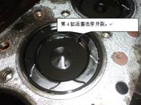

![]()
![]()
400-100-8969 15088860848
0574-26871589 15267810868
0574-26886646 15706865167
0574-26871569 18658287286
