 English
 Espaol
 Franais
 阿拉伯
阿拉伯 中文(简)
中文(简) Deutsch
 Italiano
 Português
 日本
日本 韩国
韩国 български
 hrvatski
 esky
esky Dansk
Dansk Nederlands
 suomi
suomi Ελληνικ
 印度
印度 norsk
norsk Polski
 Roman
Roman русский
 Svenska
 斯坦福STAMFORD发电机常用机型有:BC16、BC18、UC224、UC274、HC4、HC5、LV6、HC7。

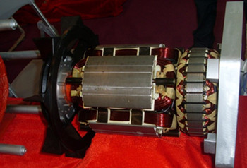
 斯坦福发电机简介
康明斯发电机技术(中国)有限公司(原无锡新时代交流发电机有限公司)是康明斯发电机技术系统在中国的唯一的独资企业,首期投资1760万美元。成立于1996年2月,于1997年11月正式开业。目前年生产能力为65,000台发电机。
 康明斯发电机技术系统有50多年成功地满足顾客需要的经验,是世界交流发电机技术的先导,康明斯发电机技术系统拥有全球销售和服务网络,并在英国、美国、中国、印度有生产工厂。无锡工厂完全按照康明斯发电机技术系统的设计及工艺标准来制造斯坦福交流发电机。产品设计、材料、生产、试验均由英方人员直接管理控制。体积小,重量轻,技术***,性能可靠是斯坦福发电机的重要特性。
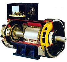
康明斯发电机技术系统制造的斯坦福发电机可与世界上所有柴油机配套,如康明斯、帕金斯、VOLVO、MTU、道依茨、卡特彼勒和国产95、130、135、150、190系列等柴油机。各系列产品成功供应发电机组成套厂家,广泛应用于铁路、船舶、邮电通信、军工、油田、交通、高层建筑及冷藏集装箱等领域。
康明斯发电机技术系统所生产的发电机系列为:BC16、BC18、UC224、UC274、HC4、HC5、LV6、HC7。功率范围为:6.5KW-2000KW。HC系列的发电机为无刷旋转磁场结构,电压最高达660V/50HZ或60HZ,满足BS5000标准第三部分和其他国际标准。在HC4,HC5,HC6/LV6,HC7四个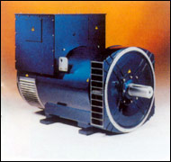 机座号中,200KW-2000 KW范围内,可选1500rpm(50HZ)或1800rpm(60HZ)、4极的发电机。在HC6/LV6和HC7两个机座号中,224KW-1300KW范围内,可选1000rpm(50HZ)或1200rpm(60HZ)、6极的发电机。机座号位HC4和HC5的发电机,其励磁系统可为使用AS440或SX421AVR的定子供电或为使用MX341或MX321AVR的永磁发电机(PMG)励磁,机座号位HC6/LV6和HC7的发电机使用MX341或MX321AVR的永磁发电机(PMG)励磁系统。
自励AVR控制的发电机,主机定子通过AS440(或SX421)AVR为励磁机磁场提供励磁源,AVR是调节励磁机磁场励磁电流的控制装置。AVR根据来自主机定子绕组的电压感应信号作出反馈,通过控制低功率的励磁机磁场调节励磁机电枢的整流输出功率,从而达到控制主机磁场电流的要求。AS440AVR通过感应两相平均电压,确保较高的电压调整率,除此之外,它还监测发动机的转速,如低于预选转速(HZ)设定,则相应降低输出电压,以防止发动机低速时的国力,缓减加载时的冲击,以减轻发动机的负担。SX421除了AS440的特点外,还具有三相均方根感应的特点,在与外部断路器(装在开关板上)一起使用时,它还提供过电压保护。
永磁发电机(PMG)励磁发电机通过MX341(或321)AVR为励磁机提供励磁源,AVR是调节励磁机励磁电流的控制装置。如果是MX321AVR,则通过一个隔离变压器向来自主机定子绕组的电压感应信号作出反馈,通过控制低功率的励磁机磁场,调节励磁机电枢的整流输出功率,从而达到控制主机磁场电流的要求。PMG系统提供一个与定子负载无关的恒定的励磁电源,提供较高的电动机启动承受能力,并不受非线性负载(例如可控硅直流电动机)产生的主机定子输出电压的波形畸变的干扰。MX341AVR通过检测二相平均电压来确保较高电压的调整率,另外它还检测发动机转速,如低于预选的转速设定,则相应降低输出电压,以防止发动机低速时的过励,缓减加载时的冲击,以减轻发动机的负担。它还提供延时的过励保护,在励磁机磁场电压过高的情况下对发电机灭磁。MX321除提供MX341巨友的保护发动机的减荷特性外,还具有三相均方根检测和过电压保护的特点。
 STAMFORD 发电机是按照国际最高质量标准,配备精心选择的零部件,采用***的世界级工艺制造而成。其能适应恶劣环境的全H级绝缘和最佳效率设计的绕组尤其适合于特殊场合的应用,标准的12个可重接出线头确保满足各种电压要求。国际品牌、人性化设计和一流服务使STAMFORD拥有众多的终身客户和广阔的应用领域。
斯坦福发电机(SX440 460 321 341 AVR)故障维修查找
1、机组起始时无电压:
a、检查线路 K1--K2
b、检查转速
c、检查剩磁电压,按外界励磁试验法步骤检查发电机和 AVR(在机静止时拆下 AVR上的 X和 XX的连线启动机组并测试 P2-P3,停机重新接上 X和 XX导线,如果测得电压大于 5V则发电机应能正常工作,低于 5V用一个直流电池负极接 XX线柱,正极通过一个二极管接 X线柱。二极管为 1A/1000V,起机 P2-P3间应有 170-250V电压,拆下电池后仍无电压查找绕组 AVR和旋转二极管。查找永磁发电机 PMGP2P3P4间电压应 170-180V/50HZ,200-216V/60HZ,若不均衡,停机从非驱动端将 PMG输出导线插件断开,检查 P2P3P4连线测定子电阻应在 2.3Ω±10%,否则定子不行,若电压均衡但电压偏低阻值正常,转子应更换)。
2、空载或负载时电压不稳
a、检查转速稳定性
b、检查稳定性设置(顺时到底逆时到开始电压波动再顺时针一
点到平稳)
3、空载或负载时电压过高
a、检查转速
b、检查发电机负载是否容性负载(功率因数超前)
4、空载时电压过低
c、检查转速
d、检查接线 1-2或外接手动微调是否连接完好
5、负载时电压过低
a、检查转速
b、检查 UFRO设置(检查发动机和 AVR)
电动机故障
1、电机不能启动: a、缺相 b、熔体烧断 c、绕组接地或相间匝间短路
2、电机外壳带电: a、绕组接地 b、绕组受潮,绝缘老化
3、电机运行时,电流表指针不稳摆动: a、转子导条开焊或断条
4、绝缘电阻低: a、绕组受潮或被水淋湿 b、绕组绝缘沾满灰尘油污 c、引出线绝缘老化破裂
d、绕组绝缘老化
5、电动机运行时有杂音、不正常: a、轴承磨损有故障 b、定转子铁芯松动 c、绕组有故障(如短路) d、轴承缺少润滑脂 e、定转子相擦或较大的砂粒进入气隙 f、系统转动惯量小
6、电机过热或冒烟: a、气隙中积满灰尘 b、电机内外积满尘土或异物影响电机散热 c、导条断裂或开焊 d、绕组匝间短路或接地 e、电机两相运转
7、电动机振动: a、轴承磨损 b、导条断裂开焊 c、绕组故障(短路断路接地等) d、铁芯变形或松动 e、皮带轮安装不当 f、电机地脚螺栓松动
8、轴承发热超过规定值: a、润滑脂过多或过少 b、油质不好或含杂质 c、轴承有故障,磨损,有杂物等 d、皮带轮偏小或皮带过紧 e、轴承油隙过大或过小
㈡电路保险丝熔断:更换保险丝。
多台柴油发电机组并机并网运行的优缺点与发电机并网解裂系统 一.发电机组并列运行的条件是什么?发电机组投入并列运行的整个过程叫做并列。将一台发电机组先运行起来,把电压送至母线上,而另一台发电机组启动后,与前一台发电机组并列,应在合闸瞬间,发电机组不应出现有害的冲击电流,转轴不受到突然的冲击。合闸后,转子应能很快的被拉入同步。(即转子转速等于额定转速)因此发电机组并列必须具备以下条件:
1.发电机组电压的有效值与波形必须相同.
2.两台发电机电压的相位相同.
3.两台发电机组的频率相同.
4.两台发电机组的相序一致.
二、什么叫发电机组的准同期并列法?怎样进行同期并列?
准同期就是准确周期。用准同期法进行并列操作,发电机组电压必须相同,频率相同以及相位一致,这可通过装在同期盘上的两块电压表、两块频率表以及同期表和非同期指示灯来监视,并列操作步骤如下:
将其中一台发电机组的负荷开关合上,将电压送至母线上,而另一台机组处在待并状态。
合上同期开头,调节待并发电机组的转速,使它等于或接近同步转速(与另一台机组的频率相差在半个周波以内),调节待并发电机组的电压,使其与另一台发电机组电压接近,在频率与电压均相近时,同期表的旋转速度是越来越慢的,同期指示灯也时亮时暗;当待并机组与另一台机组相位相同时,同期表指针指示向上方正中间位置,同期灯最暗,当待并机组与另一台机组相位差最大时,同期表指向下方正中位置,此时同期灯最亮,当同期表指针按顺时针方向旋转时,这说明待并发电机的频率比另一台机组的频率高,应降低待并发电机组的转速,反之当同期表指针按逆时针方向旋转时,应增加待并发电机组的转速。当同期表指针顺时针方向缓慢旋转,指针接近同期点时,立即将待并机组的断路器合闸,使两台发电机组并列。并列后切除同期表开关和相关的同期开关。
三、在进行发电机组的准同期并列时,应注意什么?
准同期并列是手动操作,操作是否顺利与运行人员的经验有很大的关系,为防止不同期并列,下列三种情况不准合闸。
1.当同期表指针出现跳动现象时,不准合闸,因为同期表内部可能有卡带现象,反映不出正确的并列条件。
2.当同期表旋转过快时,说明待并发电机组与另一台发电机 组的频率相差太大,由于断路器的合闸时间难以掌握,往往使断路器不在同期点合闸,所以此时不准合闸。
3.如果同期表指针停在同期点上不动,止时不准合闸。这是因为断路器在合闸过程中如果其中一台发电机组的频率突然变动,就有可能使断路器正好合在非同期点上。
四、怎样调整并列机组的逆功现象?
当两台发电机组空载并列后,会在两台机组之间,产生一个频率差与电压差的问题。并且在两台机组的监视仪表上(电流表、功率表、功率因数表),反应出实际的逆功情况,一种是转速(频率)不一致造成的逆功,另一种是电压不等造成的逆功,其调整如下:
1.频率造成逆功现象的调整:
如果两台机组的频率不等,相差较大时,在仪表上(电流表、功率表)显示出,转速高的机组电流显示正值,功率表指示为正功率,反之,电流指示负值,功率指示负值。这时调整其中一台机组的转速(频率),视功率表的指示进行调整,把功率表的指示调整为零即可。使两台机组的功率指示均为零,这样两台机的转速(频率)基本上一致。但是,这时电流表仍有指示时,这就是电压差造成的逆功现象了。
2.电压差造成逆功现象的调整:
当两台机组的功率表指示均为零时,而电流表仍然有电流指示(即一反一正指示)时,可调整其中一台发电机组的电压调整旋钮,调整时,视电流表与功率因数的指示进行。将电流表的指示消除(即调整为零),电流表无指示后,这时视功率因数表的指示,把功率因数调至滞后0.5以上即可.一般可调整至0.8左右,为最佳状态。
五、发电机保护回路
1.逆功
逆功现象是由发电机组转速(频率)及电压不同而造成的,即一台发电机组带正功,而另一台机组带负功率。也就是说带负功率的机组,这时变成了一个负载(此机组频率低,转速不一致的现象)。电压不相同时,电压高的机组,向电压低的机组,提供一个无功电流与无功电压(此机组的电流表正向指示),相当于在本供电系统内,加了一个调相机组。电压低的机组,这时成为一个大的负载,接受一个很大的无功电流,来维持两台机组的电压平衡(此机组的电流表反向指示)。监测时把某一台机组的电压调高,或将另一台机组电压高低,造成一台机组有逆功电流,其动作电流为额定电流20%左右。逆动继电器动作、跳闸、报警,但不停机。
2.过电流:
现在的发电机组额定功率一定的,它的超载能力很低,基本上在额定功率的5%左右,允许带载时间15~30分钟,最多不超60分钟,超过这个时间,发电机组会发热,导线绝缘会降低,也就降低了使用寿命。所以在设定过电流保护时无特殊要求的,过电流保护设定在额定电流的110%即可。带载测试时,将电流带至额定流的110%,过流继电器动作。跳闸、报警、不停机。
3.过电压:
在并列使用发电机组时最怕供电系统发生振荡,一但发生振荡系统电压升高,易造成用电设备及供电设备的绝缘击穿,使供电设备与用电设备一起瘫痪。为此并列使用的发电机组均装有过电压保护,其设定值为额定电压的105%为最佳。短接过电压继电器,跳闸停机、报警动作。(六)分合闸回路
分、合闸回路均接入手机并列,自动并列的控制回路。
1.手动分合闸:每台机组均可做为首机或待并分、合闸使用,在手动并车或供电时,使用手动分合闸。
2.自动分合闸:每台机组均可选择为待并机组,或首台机组;首机机组自启动后,合闸回路自动合闸,自动投入及退出同期。同期后把待并机组自动合闸并列运行。
3.无论是手动合闸,还是自动合闸,一旦机组出现逆功,过了低油压、高水温、高水温、高油温、过电压,全部自动分闸解列与负载脱离。
(七)同期回路
1.当首机合闸后把电源送至母线,这时母线检测同期回路,与待并机的同期回路,接到信号后,自动合上同期检测继电器。将母线电压与待并机电压送至同期控制模块,模块自动检测,并列机组的电压与转速。如果转速有差别时,同期模块自动调整待并机转速,使其达到并列条件。找到同期点后同期模块发出合闸指令,待并机组接到指令后执行合闸,即两台机组并列运行。
2.机组并列后,同期回路自动退出工作状态,但必须人为的把自动同期的转换开关退出,防止来电后在解列时,待并机组又接到并列信号,将同期装置自动投入,使机组再次并列。
(八)负载分配
1.单机运行时,负载分配器不投入工作。
2.机组并列后每台机组的负载分配器,同时投入工作,各自调整自已的转速,使其两台机组的功率平均分配,其工作原理,就是根据本机组的输出功率的大小(即电流的大小),自动调整丁机组的转速,使其负载平衡。
(九)电压调整回路:
1.机组并列前,必须把两台机组的电压调整在同一数值上。
2.空载并列后,调整电压旋钮,把逆功现象消除,使其功率因数在滞后0.8左右即可。
3.并列机组带载后,可根据负载情况,手动调节电压调整旋钮,使其功率因数在最佳位置,以后可不用再调整。
(十)速度调整回路:
1.并列前必须把两机组的速度(频率)调整一致。
2.并列时,可根据同期表的转动速度,调节首机或待并机组的转速,使同期表转动方向,按顺时针或逆时针方向转动,速度越慢越好,但同期表的指针必须转动才能并列。
3.并列后,观察两台机组的电流、功率是否平衡,如差别太大,可调整速度旋钮,将两台机组的功率调整到一致。
(十一)仪表检测回路:
1.操作前,必须把各种相关的仪表调改至零,但功率因数表与频率表不在零处。
2.操作时,观察各种仪表的运行状态,是否符合规定(有无仪表接线接反的现象)。
3.电流、电压、要使用有关仪表与之检验一下,看指示数值是否正常。
(十二)启动回路:
1.操作前必须首先检查启动回路是否正常。
2.启动后相关元件是否能够正常工作。
3.启动机与主机的结合是否正常,能否退出。
(十三)停机回路:
1.停机电磁铁与电磁阀动作是否可靠。
2.在机组发生故障时,是否自动停机。
3.手动停机回路是否完善。
4.只需跳闸时,是否停机等现象。
Standford generator.
Cummings generator technology (China) Co., Ltd. (formerly Wuxi new era of AC generator Company Limited ) is the Cummings generator technology system in China as the sole proprietorship, the first phase investment of 17600000dollars. Was established in 1996February, in 1997November officially opened. The current annual production capacity of65000 generators.
Cummings generator technologies has more than 50 years successfully meet the needs of the customer experience, is the world leader of AC generators technology, Cummings generator technologies has a global sales and service network, and in the UK, the United States, China, has production plants in India. Wuxi factory in full accordance with Cummings generator technology system design and process standard to make Standford AC generator. Product design, materials, production, test are under direct control of the personnel. Small volume, light weight, advanced technology, reliable performance is an important characteristic of Standford turbine.
Cummings generator technology system manufactured by Standford generator can be with all the world's diesel engine matching, such as Cummings, Perkins, VOLVO, MTU, DEUTZ, caterpillar and made 95,130,135,150,190series diesel engine. The series of products successfully supply generator sets manufacturers, widely used in railway, shipping, telecommunications, military, oil, transport, high-rise buildings and areas such as refrigerated containers.
Cummings generator technologies produced by the generator series : BC16, BC18, UC224, UC274, HC4, HC5, LV6, HC7. Power range:6.5KW2000KW. HC series generators for brushless rotary magnetic field structure, the voltage up to 660V/50HZ or 60HZ, to meet the BS5000standard third parts and other international standards. In HC4, HC5, HC6/LV6, HC7, four model,200KW-2000KW range, optional 1500rpm (50HZ ) or 1800rpm (60HZ ),4 pole generator. In HC6/LV6and HC7two model, the range of 224KW-1300KW, optional 1000rpm (50HZ ) or 1200rpm (60HZ ),6 pole generator. The base number of a HC4and the HC5 generator, the excitation system can use AS440 or SX421AVR stator power supply or for the use of MX341or MX321AVR permanent magnet generator ( PMG ) excitation, the base number of a HC6/LV6and the HC7 generator using MX341 or MX321AVR permanent magnet generator ( PMG ) excitation system.
Self control AVR generator stator, the host through AS440( or SX421) AVR exciter field provides the excitation source, AVR is the regulation of exciter field excitation current control device. From the host AVR according to stator winding voltage sensing signal feedback, by controlling the low power of the exciter field adjusting armature excitation rectifier output power, so as to control the host magnetic current requirements. AS440AVR through the induction phase average voltage, ensure high voltage regulation rate, in addition, it also monitors the speed of the engine, such as lower than a preselected speed ( HZ ) setting, is correspondingly lower output voltage, to prevent the engine at low speed and strength, reduce the impact load, in order to reduce the burden of engine. SX421in addition to AS440features, but also has three phase RMS sensing characteristics, in contact with the external circuit breaker ( installed in the switch board ) when used together, it also provides overvoltage protection.
Permanent magnet generator ( PMG ) excitation generator through MX341( or 321) AVR exciter provides excitation source, AVR is the regulation of exciter field current control device. If it is MX321AVR, through an isolation transformer to from the main stator winding voltage sensing signal feedback, by controlling the low power of the exciter magnetic field, adjusting armature excitation rectifier output power, so as to control the host magnetic current requirements. The PMG system provides a stator is independent of the load with constant power excitation, provide higher motor starting capacity, is not affected by nonlinear load ( e.g. silicon controlled DC motor ) produced by the host in the stator output voltage waveform distortion disturbance. MX341AVR by detecting the phase average voltage to ensure higher voltage regulation rate, and it also detects the rotation speed of the engine, such as less than a preselected speed setting, the corresponding output voltage is reduced, to prevent the engine at low speed of over excitation, reducing load impact, in order to reduce the burden of an engine. It also provides delay over excitation protection, the exciter field high voltage of generator. MX321provides a MX341friends of the giant engine protection of load reduction characteristics, but also has three phase RMS detection and overvoltage protection characteristic.
The STAMFORD generator is in accordance with the highest international quality standards, with careful selection of components, the use of advanced world class manufacturing process is made. It can adapt to bad environment the whole class H insulation and optimal design of winding efficiency is especially suitable for special applications, the standard 12reclosable outlet head to ensure that meet the requirements of various voltage. International brand, the humanized design and first-class service make STAMFORD has many customers for life and wide application area.
A plurality of diesel generator and grid to run the advantages and disadvantages and generator cracking system
A generating set parallel operation conditions?
Generating units put into operation in parallel of the whole process is called the. A generator to run, the voltage into a bus, while the other units after the start, with a generating set parallel, in the closing moments, generator should not appear detrimental impact on current, the rotating shaft is not affected by the sudden impact. After closing, the rotor can be quickly pulled into synchronization. (i.e., the rotational speed of the rotor is equal to the rated speed ) thus generating set parallel must meet the following conditions:
1generator voltage effective value and waveform must be the same.
2two generator voltage phase difference.
3two generating units of the same frequency.
4two generating units of the sequence.
Two, what is the generator quasi synchronization method? How to carry out the corresponding parallel?
Quasi synchronization is accurate cycle. Using quasi synchronization method for parallel operation, generator voltage must be the same, the same frequency and phase, which can be installed in the same period through the disc on two pieces of voltage meter, two frequency table and corresponding table and non synchronous indicating lamp to monitor, the operation steps are as follows:
Which will be of a generating unit load switch is closed, the voltage into a bus, while the other units in the standby state.
Close period beginning, adjusting to and turbine speed, making it equal to or near synchronous speed ( and other units of the frequency difference in half within, adjusting to Zhou Bo ) and generator voltage, and the other a generator voltage close, in the frequency and voltage are similar, earlier table rotation speed is more and more slow, synchronous indicating lamp is light and dark; when other units and units with the same phase, corresponding table pointer to founder on middle position, light the darkest period, when the unit and the other units and the phase difference of the same table, underneath the central position, this time, period lamp the brightest, when the same table pointer rotates clockwise direction, indicating that the standby generator frequency than the other units should be to reduce the high frequency, and turbine speed, and when the same table pointer according to the anticlockwise direction of rotation, and should be added to generator speed. When the same table pointer slowly clockwise rotation, the pointer near synchronous point, immediately will stay and unit circuit breaker closing, make two generating set parallel. After resection of switches and associated synchronous switch table.
Three, the generator quasi-synchronization, should pay attention to what?
Quasi synchronization is manually operated, the operation is successful and the experience has the very big relations, in order to prevent synchronization, the following three conditions to closing.
1 when the earlier table pointer appears beating phenomenon, not closing, because the same time table may have an interior cassette phenomenon, does not reflect the correct coordinate conditions.
2 when the same table rotates too quickly, and that to generating unit with another generator group of the frequency difference is too large, the circuit breaker closing time is difficult, often make the circuit breaker in the same point of closing, so that no closing.
3 if the earlier table pointer in the same point and does not move, not closing time. This is because the circuit breaker in the closing process if one generator frequency of sudden change, it is possible that circuit breaker are just in a synchronization point.
Four, how to adjust the unit inverse power phenomenon?
When the two generating units of no-load juxtaposed, in between two units, generating a difference frequency and voltage difference problems. And in the two units of monitoring instrument (current meter, power meter, power factor table ), reflect practical inverse power, a speed ( frequency ) caused by the disagreement of the inverse power, the other is a voltage range caused by the inverse function, the adjustment is as follows:
The 1frequency to cause inverse power phenomenon adjustment:
If the two units of different frequencies, difference is larger, on the instrument (current meter, power meter ) show, high speed unit current display positive, power indicator for positive power, conversely, current indicating negative, negative power indicator. The adjustment of one unit speed ( frequency ), apparent power meter indication adjustment, the power meter indication adjusting zero. The two units of power indication are zero, so the two machine speed ( frequency ) basically consistent. However, the current table still have the instructions, this is the voltage difference to cause the phenomenon of inverse function.
The 2voltage difference caused by the phenomenon of inverse power adjustment:
When two units of power meter are zero, and the current meter is still current indication ( i.e. a positive indication ), adjustable wherein a generator voltage adjusting knob, adjust, as the current and power factor of the instructions. The current table indicating elimination (i.e. adjust to zero ), ammeter without instructions, then considered the power factor meter indication, the power factor at lag 0.5above can. Can generally be adjusted to about 0.8, as the best state.
Five, the generator protection circuit
1inverse function
Inverse power phenomenon is produced by the generator speed ( frequency ) and voltage caused by the different, namely a generating unit with positive power, and the other one unit with a negative power. That is to say with negative power unit, then became a load ( the frequency is low, speed inconsistencies ). Voltage phase at the same time, high voltage unit, to the low voltage unit, providing a reactive current and reactive power voltage ( the unit of current meter positive indication ), equivalent in the power supply system, and a condenser group. Low voltage unit, then become a big load, receiving a very reactive current, to maintain the two units of voltage balance ( the unit of current meter reverse indicator ). Monitoring of a unit of voltage is high, or the will of another unit voltage, resulting in a unit has an inverse reactive current, the operating current and rated current is about 20%. Inverse relay action, tripping, alarm, but do not stop.
2 overcurrent:
Now the rated reactive power necessarily, the overload capacity is very low, basically in the rated power of about 5%, allows the load time 15~30minutes, most do not exceed 60minutes, over this time, generating units will be fever, the insulation of the wire can be reduced, but also reduces the use of life. So in the setting of overcurrent protection without special requirements, overcurrent protection setting in the rated current of 110%. On load test, the current band to the rated flow of 110%, overcurrent relay. Trip, alarm, don't stop.
The 3voltage:
In the parallel use of generating units at the most feared power system oscillation, in the event of a vibration system voltage increase, easy to cause electrical equipment and power equipment insulation breakdown, make power supply equipment and electric equipment with paralysis. The parallel use of generating units are equipped with over voltage protection, the set values for the rated voltage of105% is the best. Short over voltage relay, tripping, the alarm action. ( six) switching circuit
Points, closing circuit are connected in parallel by mobile phone, automatic control loop.
1manual closing: each unit can be led by machine or stay and closing, use, manual and car or power supply, using a manual switch.
2automatic switching: each unit may choose to stay and unit, or the first unit; the first unit after startup, the closing loop automatic closing, automatic operation and withdrawal period. Over the same period after the stay and automatic closing parallel operation.
3either manual or automatic switching, switching, once the unit inverse power, the low oil pressure, high water temperature, high temperature, high temperature, voltage, full automatic gates line and load from.
( seven) synchronous circuit
1when the first machine after closing the power delivered to the bus, the bus detection synchronous circuit, and wait and the machine synchronous circuit, after receiving signals, automatically close the synchronism check relay. The bus voltage and the machine voltage to synchronization control module, module automatic detection, the unit of voltage and rotating speed. If the speed is different, corresponding module automatically adjust wait and the machine speed, the parallel condition. Synchronization synchronization module sends found after switch-on instructions, and after receiving the instruction execution unit to be closed, i.e. two units in parallel operation.
2set parallel, synchronous loop automatic quit working state, but must be regarded the automatic synchronization switch exit, prevent the call after the solution column, stay and unit also received a parallel signal, synchronizing device will automatically input, make the unit again tied.
( eight) load distribution
The 1single unit operation, load distributor does not work.
2set parallel after each unit load distributor, at the same time into work, adjusting their own speed, making it the two units of average power allocation, its working principle, is based on the unit power output size (i.e. current size), automatic adjustment D unit speed, so that the load balance.
( nine) voltage adjusting circuit:
1set parallel, must have two units of voltage adjustment at the same value.
2no-load juxtaposed, voltage adjustment knob, the inverse power phenomenon is eliminated, so that the power factor at lag 0.8or so can.
3 parallel unit load, can according to the load, manually adjustable voltage adjusting knob, so that the power factor at the optimum position, later can not be adjusted.
( ten) speed adjusting circuit:
The 1parallel before must take two unit speed ( frequency ) adjusted agreement.
The 2 parallel, according to the same table rotating speed, regulating first machine or stay and unit speed, so that the same table rotation direction, clockwise or anticlockwise rotate speed, the slower the better, but the table pointer must turn to the.
Parallel observation after3, two units of current, power balance, such as difference too big, can adjust the speed of the knob, two units of power to align.
( eleven) instrument detecting circuit:
1before operation, must take a variety of related instrument modified to zero, but the power factor meter and frequency meter is not in zero.
2operation, observe the various instruments
