三相同步发电机的工作原理控制及维护保养原理
柴油发电机组是常用的备用电源,由于它以柴油发动机燃烧柴油为动力,带动发电机发出与市电同样性质的电力,所以用在市电断电后需要后备电源供电几小时以上的场合。从性能价格比、对工作环境的要求、带非线性负载能力方面考虑,采用柴油发电机组比使用很多大容量蓄电池的长延时UPS往往具有一定的优势。但是柴油发电机组在市电断电后需要十秒钟左右才能发出稳定的电力,这就大不如UPS可不间断供电的特点。因此,柴油发电机组和UPS通常是取其各自的优势构成一个完善的、可靠的电源系统,以确保重要设备的不间断供电。
柴油发电机组一般是采用同步发电机(也俗称电球)将柴油发动机的旋转机械能转为电能。各种用电设备要依靠它发出的电力工作,因此对同步发电机的工作性能要求是很高的。
1 同步发电机的工作原理
同步发电机是根据电磁感应原理制造的。主要组成部分如图1。现代交流发电机通常由两部分线圈构成;为了提高磁场的强度,一部分线圈绕在一个导磁性能良好的金属片叠成的圆筒内壁的凹槽内,这个圆筒固定在机座上称为定子。定子内的线圈可输出感应电动势和感应电流,所以又称其为电枢。发电机的另一部分线圈则绕在定子圆筒内的一导磁率强的金属片叠成的圆柱体的凹槽内,称为转子。一根轴穿过转子中心并将其紧固在一起,轴两端与机座构成轴承支撑。转子与定子内壁之间保持小而均匀的间隙且可灵活转动。这叫做旋转磁场式结构的无刷同步发电机。
工作时,转子线圈通以直流电形成直流恒定磁场,在柴油机的带动下转子快速旋转,恒定磁场也随之旋转,定子的线圈被磁场磁力线切割产生感应电动势,发电机就发出电来。
1—前端盖;2—出风盖板;3—轴承;4—定子;5—端子箱侧板;6—电压调节器;7—调节器支架;8—端子箱顶盖;9—端子箱前后板;10—接线板;11—接线板支架;12—端子箱侧板;13—吊攀;14—轴承盖;15—进风盖板;16—后端盖;17—励磁定子;18—励磁定子固定螺栓;19—轴承;20—旋转整流器;21—励磁电枢;22—接地牌;23—转子;24—风扇;25—永磁机机壳;26—永磁机转轴;27—永磁机转子;28—永磁机定子;29—永磁机定子固定螺栓;30—永磁机转子固定螺栓;31—垫圈;32—永磁机盖板
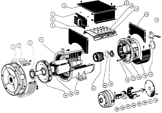
图1 双轴承发电机剖视图
转子及其恒定磁场被柴油机带动快速旋转时,在转子与定子之间小而均匀的间隙中形成一个旋转的磁场,称为转子磁场或主磁场。平常工作时发电机的定子线圈即电枢都接有负载,定子线圈被磁场磁力线切割后产生的感应电动势通过负载形成感应电流,此电流流过定子线圈也会在间隙中产生一个磁场,称为定子磁场或电枢磁场。这样在转子、定子之间小而均匀的间隙中出现了转子磁场和定子磁场,这两个磁场相互作用构成一个合成磁场。发电机就是由合成磁场的磁力线切割定子线圈而发电的。由于定子磁场是由转子磁场引起的,且它们之间总是保持着一先一后并且同速的同步关系,所以称这种发电机为同步发电机。同步发电机在机械结构和电器性能上都具有许多优点。
2 同步发电机的调控
同步发电机在其额定负载范围内允许带各种用电负荷。这些负荷的输入特性会直接影响发电机的输出电压;当负载为纯电阻性时,因为同步发电机的定子端电压——电枢端电压与负载电流是同相的,所以使得转子磁场的前一半被定子磁场削弱,而后一半又被定子磁场加强,一周内合成磁场平均值不变,发电机输出电压不变。负载呈现为纯电感性时,则因负载电流滞后电枢端电压90°而使得定子磁场削弱了转子磁场,合成磁场降低,造成发电机输出电压下降。若负载是纯电容性的,负载电流就会超前电枢端电压90°,从而使定子磁场加强了转子磁场,合成磁场增大,发电机输出电压上升。可见;合成磁场是使发电机性能变化的一个重要因素。而合成磁场中起主要作用的是转子磁场即主磁场,因此,调控转子磁场就可以调节同步发电机的输出电压改善其带负载能力,从而达到在额定负荷范围内稳住发电机输出电压的目的。
(1)同步发电机转子的励磁
所谓励磁即是向同步发电机转子提供直流电使其产生直流电磁场的过程。同步发电机转子凹槽内的线圈就是由称做励磁机的一个专门的设备为其供以直流电形成直流磁场的。早期的发电机是采用单独的励磁机给转子线圈提供直流电的,系统庞大而复杂。随着技术的进步,现代同步发电机都是将发电机与励磁机组装在一起构成一个完整的发电机。
励磁机其实就是个小发电机,它的工作原理与同步发电机一样。所不同的是它的定子线圈和转子线圈所起的作用与同步发电机——主发电机正好相反;固定在主发电机定子旁的励磁机的定子线圈通以直流电形成直流磁场,而安装在主发电机转子轴上的励磁机的转子线圈成为输出电动势的电枢。励磁机的转子与定子内壁之间也是保持着小而均匀的间隙。这也称为旋转电枢式结构的无刷同步发电机。安装在主发电机定子旁的励磁机定子线圈的直流电,是由主发电机定子线圈即电枢的部分输出电压经整流后而得到的。与主发电机转子同轴安装的励磁机转子线圈在其定子线圈产生的磁场内旋转、切割磁力线所产生的感应电动势,经同轴安装在它旁边的整流器也就是旋转整流器变成直流电流,输到主发电机的转子线圈使其产生直流转子磁场。从而达到了对主发电机转子线圈励磁的要求。
(2)同步发电机输出电压的调控
调控的目的就是实现在同步发电机额定负荷范围内稳住输出电压。调控技术的理念是实时地从主发电机电枢取得电压和电流,经整流和负反馈调理后供给励磁机的定子线圈,使其产生变化规律与主发电机输出电压变化规律相反的直流电磁场,这个磁场也必然使励磁机转子电枢的输出电压及旋转整流器供给主发电机转子线圈的直流电流按同样的规律而变化。从而起到实时调节主发电机转子磁场大小,使主发电机在额定负荷范围内保持良好输出特性的作用。
Three phase synchronous generator working principle and maintenance of control principle
Diesel generating sets are commonly used in standby power supply, because it to diesel engines burning diesel as power, drive the generator to generate electricity and the city of the same nature power, so in the electric power need backup power supply for several hours or more occasions. From the ratio of performance to price, the requirements on the working environment, with nonlinear load capacity is taken into consideration, the use of diesel generators than the use of a lot of large capacity storage battery long time delay UPS often has certain advantages. But the diesel generating set in the city of electric power needs about ten seconds to make a stable power, which is much larger than the UPS uninterruptible power supply characteristics. Therefore, diesel generating sets and UPS is usually take their advantages to form a perfect, reliable power supply system, to ensure the important equipment of uninterrupted power supply.
Diesel generator set is generally adopted in synchronous generator ( also known as electric ball ) diesel engine rotating mechanical energy into electric energy. A variety of electrical equipment to rely on it sends the electrical work, so the synchronous generator performance requirements are very high.
1the principle of a synchronous generator
Synchronous generator is based on the electromagnetic induction principle manufacturing. The main part of figure 1. Modern AC generator typically consists of two portions of the coil form; in order to improve the strength of the magnetic field, a portion of the coil wound on a magnetic properties of good metal lamination of the cylinder inner wall of the groove, the cylinder is fixed on the frame referred to stator. Stator coil can output the induced electromotive force and induced current, so also known as the armature. Generator and another part of the coil is wound on the stator cylinder of a permeability strong metal sheet laminated cylindrical groove, called rotor. A shaft extends through the center of the rotor and fasten together, both ends of the shaft and the base form bearing support. The rotor and stator inner wall between remain small and uniform gap and can rotate flexibly. This is called a rotary magnetic field type structure of brushless synchronous generator.
When working, the rotor coil with DC DC magnetic field is formed, in the diesel engine driven rotor spun, constant magnetic field is rotated, the stator coil by the magnetic field lines cutting to produce induced electromotive force, the generator can generate electricity.
1 - front cover;2, a wind cover plate;3 - bearing;4 - stator;5 - terminal box side plate;6, voltage regulator;7 - regulator bracket;8 - terminal box cover;9 - terminal box front plate;10 - terminal plate;11 - wiring board bracket;12 - terminal the side box;13, a lifting;14 - bearing cap;15 - air inlet cover;16 - rear cover;17, the stator of the exciter;18, the stator of the exciter fixing bolt;19 - bearing;20 - rotating rectifier;21, the exciter armature;22 - Grounding card;23, the rotor;24 - fan;25 - permanent magnet machine;26 - permanent magnet machine rotating shaft;27 - permanent magnet machine rotor;28 - permanent magnet machine stator;29 - permanent magnet machine stator fixing bolt;30 - permanent magnet machine rotor retaining bolt;31 - washer;32 - permanent magnet machine cover
Fig 1 the double bearing generator section view
The rotor and the magnetic field is a diesel engine to drive a fast rotation, between the rotor and the stator are small and uniform gap in the form of a rotating magnetic field, known as the rotor magnetic field or magnetic field. The normal work when the generator stator whereby the armature is connected with a load, the stator coil is the magnetic field lines after cutting the induced electromotive force generated by the load currents induced in the formation, the current flowing through the stator coils can generate a magnetic field in the gap, known as the stator magnetic field and armature magnetic field. When the rotor, stator between small and uniform gap has emerged in the rotor magnetic field and stator magnetic field, the two magnetic field interactions constitute a composite magnetic field. The generator is composed of synthetic magnetic field of the magnetic lines cutting stator coil and power. Due to the magnetic field of the stator is composed of rotor magnetic field is induced, and they always keep one after the other and the same speed synchronization relationship, so that the generator for synchronous generator. Synchronous generator in the mechanical structure and electrical properties has many advantages.
2synchronous generator control
Synchronous generator at its rated load range allowed a variety of electric load. These load input characteristics will directly affect the output voltage of the generator; when the load is purely resistive, for synchronous generator stator terminal voltage -- the armature terminal voltage and the load current are in phase, so that the magnetic field of the rotor stator magnetic field weakening before the half, and the second half was the stator magnetic field strengthening, within a week of the resultant magnetic field average constant value, the output voltage of the generator. Load show pure inductive, is due to the load current hysteresis armature voltage90 °and the weakening of the magnetic field of the rotor magnetic field decreases, synthesis, resulting in the generator output voltage drop. If the load is purely capacitive, load current will lead the armature voltage90 degrees, so that the stator magnetic field enhanced rotor field, resultant magnetic field increases, the output voltage of the generator to rise. Synthesis of magnetic field is visible; make generator performance change is one of the important factors. Synthesis of magnetic fields and played a major role in the magnetic field of the rotor is the main magnetic field, therefore, regulation of rotor magnetic field can adjust the synchronous generator output voltage to improve the load capacity, so as to achieve the rated load range to stabilize the output voltage of the generator to.
(1) the excitation of synchronous generator rotor
The excitation of synchronous generator rotor is to provide DC power to the DC electromagnetic process. Synchronous generator rotor groove is called exciter coil by a specialized equipment for its formation for DC DC magnetic field. Early generator is used to separate the exciter rotor coil to provide DC power to the system is large and complex. With the development of technology, modern synchronous generator is the generator and exciter assembled together constitute a complete generator.
The exciter is actually a small generator, its working principle and the synchronous generator. The difference is that the stator coil and the rotor coil the role of main generator and synchronous generator -- just the opposite; fixed in the main generator stator adjacent to the stator of the exciter coil with DC DC magnetic field is formed, and is mounted on the main rotor shaft of generator 's exciter rotor coil becomes the output electromotive force of the armature. Exciter rotor and stator inner wall is also maintained a small and uniform gap. This is also known as the revolving armature type structure of brushless synchronous generator. Mounted on the main generator stator side exciter stator coil DC, is composed of a main generator stator coil or armature portion of the output voltage is rectified obtained after the. With the main generator rotor coaxially mounted exciter rotor winding in the stator coil to generate a magnetic field in rotating, cutting the lines of magnetic force produced by the induction electromotive force, the coaxially mounted beside it is rotating rectifier rectifier into DC current, input to the main generator rotor coil of the DC magnetic field of the rotor. We can reach the main generator rotor coil excitation requirement.
(2) output of a synchronous generator voltage regulation
The purpose of regulation is to realize the synchronous generator rated load range to stabilize the output voltage. Regulation of technical philosophy is in real time from the main generator armature voltage and current by the rectifier to obtain, and the negative feedback adjust supply a stator of the exciter coil, make its produce variation and main generator output voltage variation instead of DC electromagnetic field, the magnetic field will also make the exciter rotor armature voltage and rotating rectifier supply main generator rotor coil DC current according to the same rule changes. In order to adjust the main generator rotor magnetic field, so that the main generators in the rated load range to maintain good output characteristic function.
The generator output voltage regulating process, can use the following process representation;
As the load increases the main generator armature voltage. (down ) to the negative feedback after conditioning exciter stator currents and magnetic fields up to the exciter rotor armature voltage up to rotating rectifier output current up to the main generator rotor magnetic field to make up of main generator armature voltage.
If the main generator voltage increases, the feedback control to the above each link function reduces, causes the voltage to rated value.
Visible through the exciter real-time regulation of main generator rotor magnetic field size, can stabilize the output voltage. Which play an important role in the negative feedback regulation unit, usually called constant-voltage excitation device and automatic voltage regulator.
(3) the automatic voltage regulator
Modern AC synchronous generator automatic voltage regulator AVR commonly used the electronic component regulating exciter stator magnetic field intensity. Although the AVR type are many, but the performance is similar; real-time sampling of the main generator output voltage value and the predetermined value are compared, with comparable results to the regulating pulse width modulator PWM; the output voltage value is high, narrow pulse width modulator output, whereas the width. Then these pulses to control high power switching devices such as a transistor or FET controls into the exciter stator coil current time. So that the magnetic field strength as the main generator output voltage change the opposite changes; i.e. the output voltage wave exciter stator magnetic field decreases, lowering the output voltage exciter stator magnetic field enhancement. So as to achieve the purpose of negative feedback regulation.
Figure 2 automatic voltage regulator circuit principle of Fang Kuangtu
Figure 2is a commonly used type AVR. Sampling independent generator output voltage signal from the8,9 ends and input to a voltage measuring unit of comparison, and internal predetermined voltage value ( for example380V ) phase comparison. And compare the results with the output voltage of UA into pulse width modulation unit PWM, output voltage UC into low frequency protection unit. Voltage measurement comparison unit L, S, H is connected to the main generator output voltage amplitude adjusting potentiometer three terminals.
Pulse width modulator by the regulator output DC voltage of UCC as a working power supply, in order to ensure its stable performance. Its output voltage UB control modulation tube VT3. If the voltage measurement comparison unit sent UA, shows that the output voltage of the generator is increased, the UA will enable pulse width modulator output pulse width of UB. Narrow pulse will make VT3conduction time is short, the current through the less. Conversely, the main generator voltage to reduce the UA smaller, pulse width modulator output pulse width of UB become wide, so that VT3turn-on time is long, the current increase.
Exciter stator coil end of the terminal X1, the other end of the XX1terminal. The main generator armature. EA, EB, Ec three-phase voltage, through the three diode VD10, VD11, VD12rectifier, current from the X1 end into a stator of the exciter coil, by XX1outflow, and after modulated tube VT3and XN terminals to the main generator armature, forming the exciter stator coil excitation current path. VT3 is the channel switch, conduction time is long, the stator coil current flowing through a long time, the stator magnetic field strength; VT3conduction time is short, the stator coil current, stator magnetic field intensity.
This is the AVR regulation of main generator voltage due to the load causes; main generator output voltage increases, voltage measurement comparison unit output UA increasing, UA control of the pulse width modulator output UB pulse width becomes narrower, the switch tube VT3conduction time is short, the exciter stator field weakens, the rotor armature voltage and rotating rectifier output electric current. Decrease, bring about supply main generator rotor excitation current is small, then the main generator because of its rotor magnetic field decreases so that the output voltage is reduced. Conversely, negative feedback regulation of AVR function will make the main generator output voltage rise.
The main generator for the load exceeds a rated value and output maximum current, diesel engine also subsequently output power that led to its rotational speed is lower than the rated value. Low frequency protection unit is the role of condition limiting exciter stator coil current excess increases. It composed of resistor and capacitance charge and discharge circuit set a low frequency protection, when the main generator load normal, from a voltage measuring unit of UC less than low frequency protection points, then low frequency protection unit output voltage of Ud, diode VD8is off, Ud reach the pulse width modulator, having no effect. If the main generator overload Ud becomes lower, VD8conduction, Ud and UA can simultaneously act on the pulse width modulator, the output pulse of UB with Ud decline narrowed, modulation tube VT3turn-on time become short, excitation current decreases the exciter stator magnetic field become weak, which leads to the main generator rotor magnetic field decreases. Generator output voltage, current decrease decline. Low frequency protection unit to protect the exciter and generator effect.
3synchronous generator maintenance
The synchronous generator is the key part of diesel generating set. For the diesel generator set to establish a suitable working environment, make daily maintenance is very necessary.
Generator room inside the high temperature, humidity and air pollutants are the most common factors caused by fault of generator. Dust, dirt and other air pollutants accumulation will cause the bad performance of the insulating layer, not only easy to form the conductive pathways, may also make the rotor bearing part of the friction increases heating. Moisture and air pollutants in the moisture easily in the generator of the leakage path, cause the fault of generator. Room temperature is too high will make the generator generates heat when not out, causing the output power decreases, unit overheated. So the room dust prevention, damp, ventilation cooling must cause enough attention.
Either a single or double bearing generator bearing generator, the rotor shaft and the diesel engine spindle is connected between the high requirement of coaxiality. Long period running of units sometimes coaxial may reduce, lead generator noise increases, high temperature. Should be checked regularly, in order to maintain concentricity good maintenance.
 English
 Espaol
 Franais
 阿拉伯
阿拉伯 中文(简)
中文(简) Deutsch
 Italiano
 Português
 日本
日本 韩国
韩国 български
 hrvatski
 esky
esky Dansk
Dansk Nederlands
 suomi
suomi Ελληνικ
 印度
印度 norsk
norsk Polski
 Roman
Roman русский
 Svenska